Table of Contents
Advertisement
Quick Links
Advertisement
Table of Contents

Related Manuals for Rinstrum axleWEIGHr


Summary of Contents for Rinstrum axleWEIGHr
- Page 1 (L003-507) Reference Manual...
- Page 2 Rinstrum Pty Ltd. Disclaimer Rinstrum Pty Ltd reserves the right to make changes to the products contained in this manual in order to improve design, performance or reliability. The information in this manual is believed to be accurate in all respects at the time of publication, but is subject to change without notice.
-
Page 3: Table Of Contents
Operator Manual Rev 2.01 Table of Contents – Category Logger App L003-507 OVERVIEW ........................... 2 1.1. Overview ........................2 1.4. User Interface & Display ..................... 3 1.5. Display & Annunciators ....................4 1.7. Keypad ........................5 1.9. Turning Instrument on ....................6 1.11.1 Wiring &... -
Page 4: Overview
Many of the features and functions described in this manual may not be available in all versions of the axleWEIGHr. Due to variations in Firmware and various applications not all features described in this manual may work as described. -
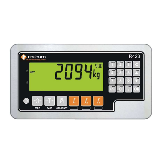
Page 5: User Interface & Display
Operator Manual Rev 2.01 User Interface and Display Code Description Display Numeric Keypad Function Keys (Fixed) Power Key Page 3 L003-507-V1.2.1... -
Page 6: Display & Annunciators
Operator Manual Rev 2.01 1.5. Display Code Description Primary Annunciators Primary Display Auxiliary Display (WO or WO-PT) Primary Units Category prompt: example Farm Miscellaneous Annunciators Secondary Units (function not available) Secondary Display (totalised weight of last truck) 1.6. Primary Annunciators Symbol Name Description... -
Page 7: Keypad
Operator Manual Rev 2.01 1.7. Keypad Code Description Number Buttons 0-9 (short press) Black Characters Hold 2 seconds (#1 key allows time & date configuration) Orange Characters [F1]-[F3]* Cancel Undo last command; step backwards (including in setup menus). Move cursor backwards; previous option (use for trucks &... -
Page 8: Turning Instrument On
Operator Manual Rev 2.01 Special keys are: <OK>: Accept changes and finish. <Long press of cancel>: Cancel and exit without changes <Cancel>: Delete character <Up>, <Down>: Move cursor <Long press of down>: Delete string after cursor ... -
Page 9: Wiring & Connections
Operator Manual Rev 2.01 1.11. Wiring & Connections Make connections using the supplied AC Power cord terminating the Grey Green and White wires as shown below. 110 VAC - 240 VAC accepted AC POWER MAIN CONNECTIONS Grey Terminal – Black (HOT) Connector 1 –... -
Page 10: Zero Key
Operator Manual Rev 2.01 1.12. Zero Key When an empty scale has drifted away from a true zero reading, this key is used to perform a zero adjustment on the scale display. The zero adjustment is stored when power is removed and is re-used when next powered up. -
Page 11: Dynamic Scale, Creating & Setting Up Trucks
With the scale at zero the dynamic scale factor can now be set. The reference weight of a fully loaded truck should be obtained at a nearby certified truck scale. Simply drive across the axleWEIGHr to capture a truck’s total weight. (See also page 20-21) CAPTURED TOTAL ON BOTTOM:... -
Page 12: Setting Time & Date
Operator Manual Rev 2.01 1.13 Creating a Permanent Truck ID (Create & Setup) (Press & Hold the Up key, set name using number pad, select 1 or 2 pass, enter tare weight if one pass.) Farm & Field selection will then prompt (see section 2.10.2.) Editing Truck Data (existing) Select the truck you want to configure. - Page 13 Operator Manual Rev 2.01 Selecting Truck IDs Select a Truck ID - Short Press of F1 (TRUCK KEY) A short press of the [F1] key will allow the user to select the desired truck from the truck list. The <UP> and <DOWN> keys will then step through the list of trucks in the truck database.
-
Page 14: Stability
Operator Manual Rev 2.01 1.15 Stability Considerations Some functions (e.g. Tare and Zero) require a stable weight. These functions will wait for up to 10 seconds for stable weight. If a stable weight is not available ‘MOTION ERROR’ is displayed and the function is cancelled. 1.16 Traffic Lights While at Zero &... -
Page 15: Clicker Operation
Press [OK] to enter learn mode. Once key fob has been press “DONE” will display. Weigh-in (2 PASS), Weigh-out pre-set tare (1 PASS), Weigh-out (2 PASS) These are the 3 screen you should see on the Rinstrum 423 display when the clicker has been activated. -
Page 16: Usb Operation
Operator Manual Rev 2.01 1.18 USB Operation When using the USB drive provided by Rinstrum you will want to search for the folder named “Data Store”. (See section 1.23) The 2 files you will be using need to be moved to the ROOT directory of the USB drive. -
Page 17: Setting Up Trucks
Operator Manual Rev 2.01 Ensure tension spring is configured for maximum tension as shown above to ensure optimal printing operation. There is a “PRINT’ test button shown in figure above used to perform a single test page. Page 15 L003-507-V1.2.1... -
Page 18: Truck Weighing
Operator Manual Rev 2.01 Truck Weighing 1.20 Weighing Once a Truck has begun to scale you can either press the clicker button/[F1] key to select the truck or do nothing and the weight will totalize and display on the lower display for a period of time. If you do nothing then the data will not be stored in the database and a ticket will not print out. -
Page 19: Function Key Operations
Operator Manual Rev 2.01 Page 17 L003-507-V1.2.1... -
Page 20: Setting Up Csv Data-Base
Long press: configure truck (last selected) [F2] Key Short press: Reprint last truck Long press: Configuration menu (This menu controls critical axleWEIGHr settings. The default menu settings should not be altered unless advised by Rinstrum/Service Company) Other Configuration: Page 18... - Page 21 Operator Manual Rev 2.01 To re-bind all wireless key fobs or to change the farm field selection methods see end of manual. Page 19 L003-507-V1.2.1...
- Page 22 Operator Manual Rev 2.01 Harvest & Truck CSV File Configuration 1.24 USB Files Select and open the harvest.csv file. An example of the harvest file is shown below. Do not change the data in the header (data inside the yellow box). To setup your farm & field data change the names to suit your farm names.
- Page 23 Operator Manual Rev 2.01 1.25 Truck.csv File editing The truck file allows for editing/ adding trucks. You can create custom names instead of the default “Truck 1”, “Truck 2” etc. The header should not be altered (The label “id”, “truck”, “pass”, “tare”) but the data below it is configurable. Id &...
-
Page 24: Data Log Output
Operator Manual Rev 2.01 Data Log Output The log.csv file contains all of the weight data for each truck including the farm and field configuration. A farm & field that does not have data details is due to the farm & field not configured. The truck was weighed before the farm database was configured for that day. -
Page 25: Error Messages
Operator Manual Rev 2.01 Error Messages 1.26 Overview A number of error messages may be displayed to warn of operation outside of the acceptable limits. These messages may appear on either the primary or the secondary display. Short messages (XXXXXX) will appear as a single message. Longer messages (XXXXXX) (YYYYYY) will appear on the display in two parts, first the (XXXXXX) part, then the (YYYYYY) part. -
Page 26: F2 Configuration Menu Defined
Operator Manual Rev 2.01 F2 Configuration Menu (long press) Timeout: Time in between axles before controller times out and complete axle captures. (default 20 sec) Discard: Timer allowing for truck id press after weighing has taken place. (default 10 sec) Dyn.Scl: dynamic scaling factor for “in-motion”... -
Page 27: Definitions & Special Settings Menu
DIAGRAM FOR MOUNTING SENSORS: See below: Definitions: Console: This can include the R423 instrument and up to the entire axleWEIGHr box including kiosk printer R423: This is the stainless indicator mounted on the front of the axleWEIGHr LUA: The lua module is located on the back of the stainless indicator nearest the... - Page 28 Operator Manual Rev 2.01 Clicker: Small black key fob used for remote id of trucks Power Supply: 120 VAC Power supply located inside the enclosure near the M12 connectors (see figure 1) SPECIAL SETTINGS MENU: Press and Hold Power & F1 together at the same time. This will enter a special settings menu and should only be done by qualified personnel.
- Page 29 Notes:...
Need help?
Do you have a question about the axleWEIGHr and is the answer not in the manual?
Questions and answers