Table of Contents
Advertisement
Quick Links
Advertisement
Table of Contents

Subscribe to Our Youtube Channel
Related Manuals for ViM PILOT PARC MASTER Series

Summary of Contents for ViM PILOT PARC MASTER Series
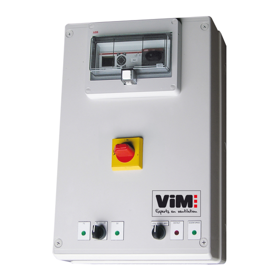
- Page 1 INSTRUCTION MANUAL INSTALLATION | WIRING | COMMISSIONING | MAINTENANCE | I S O 9 0 0 1 ISO 14001 Q u a l i t é Environnement AFNOR CERTIFICATION AFNOR CERTIFICATION PILOT PARC MASTER Unit for indoor parking facilities NT00000582-PILOT-PARC-MAITRE-AN-200723...
-
Page 2: Table Of Contents
CONTENTS GENERAL INFORMATION ........................ 3 Warnings ..........................3 Reception - Storage ......................... 4 Warranty ..........................4 PRODUCT PRESENTATION ......................5 Range ............................5 Dimensions (in mm) ........................5 Technical characteristics......................5 ELECTRICAL CONNECTION ......................6 Power supply ........................... 6 Motor power output ........................6 Maximum connection capacity and tightening torque .............. -
Page 3: General Information
We recommend that all those exposed to risks must comply with accident prevention standards. VIM can in no case be held liable for any injury or material damage due to failure to comply with the safety instructions or due to any modification to product. -
Page 4: Reception - Storage
In any event, VIM is not responsible for equipment that has been modified, repaired or disassembled even if only partially. -
Page 5: Product Presentation
PRODUCT PRESENTATION 2.1 Range Model Type of motor controlled PILOT PARC MH1DA 1 three-phase 400V 2 speed motor with Dahlander winding PILOT PARC MH1DA CMSI PILOT PARC MH2DA 2 three-phase 400V 2-speed motor with Dahlander winding PILOT PARC MH2DA CMSI PILOT PARC MH1BI 1 three-phase 400V 1- or 2-speed motor with separate windings... -
Page 6: Electrical Connection
ELECTRICAL CONNECTION 3.1 Power supply Three-phase 400V 50/60Hz + Earth, according to current standards. Connect the power supply phases directly on the switch-disconnector and the earth connection conductor on the specific PE connection strip. • If there are ready factory-fitted connections on the switch-disconnector terminals, check that they are secured after connecting the power supply. -
Page 7: Maximum Connection Capacity And Tightening Torque
3.3 Maximum connection capacity and tightening torque Data for rigid, solid conductors. PILOT PARC versions with 1 Motor Power supply Power output Control terminal block Rated current Tightening Tightening Tightening HS motor Max section Max section Max section torque torque torque (max A) (mm²) -
Page 8: Connection Diagrams: See § "8. Annexes
PILOT PARC versions with 2 Motors Control + Rated current Power supply Power output Communication HS motor (max. in A) Type Number Type Number Type Number ISO M25 ISO M25 ISO M32 ISO M25 ISO M40 ISO M32 3.5 Connection diagrams: see § "8. ANNEXES", page 14 COMMISSIONING 4.1 Preliminary remarks •... - Page 9 4.2.2 Logical processing of EASY-E4-UC controller inputs signals The automaton includes 2 parts: one basis 12RC1 (B) + one extension 8RE1 (E), items B and E in inputs names here below. Priority Input Name Action (0=highest) Switch to LS comfort if HS or Off not requested. LS comfort order Switch to HS comfort if Off not requested.
-
Page 10: Language, Clock Setting And Operation
4.2.4 Other indicators and outputs Name Indication LS indicator At least one fan is in LS mode. HS indicator At least one fan is in HS mode. “Smoke extraction active” information output for PILOT PARC excl. “CMSI” version: use the contact available on the BDRA activation unit (see §... - Page 11 4.3.2 Setting the time Start point = main screen (window 1): The box has 2 channels HW01 (LS) 1..456..9... and HW02 (HS) and each channel has programmable 4 time MA 16:10 slots A, B, C and D Q ..34.6 Q ..34.6 STOP RUN PARAMETERS MOT DE PASSE...
- Page 12 4.3.3 Modification of “LS times before switching to HS” • Factory setting = 5 seconds. • Follow steps described below to modify this setting inside the range 0-25s: Start point = main screen (window 1) 1.3456789..KEY: Time slots modi cation MA 11:40 ÏÐ...
-
Page 13: Modbus Communication
MODBUS COMMUNICATION PILOT PARC is a slave on the link. TCP / IP communication - use a CAT5 Ethernet cable with 8 pin RJ45 connector. Factory controller IP adress = 192-168.0.2 - display of the current address at the bottom right of the screen by default. -
Page 14: Maintenance
MAINTENANCE Annual visual and functional inspection or more frequently if necessary. Protection fuses: • In the control circuit: - Two labelled F1 = 1A aM / 500V (10.3x38 mm) - One labelled F2 = F3.15A / 250V (5x20mm). - For PILOT PARC ratings 150A, 185A and 225A: Two labelled F4 = 6AaM / 500V (10.3x38 mm) •... -
Page 15: Wiring Required To Use The Bcca 2V Unit
8.2 Wiring required to use the BCCA 2V unit PILOT PARC BCCA 2V MAÎTRE MASTER 0 PV GV Bornes de Connecting raccordement terminals 8.3 Wiring required to use the (1Z or 2Z) BCCP unit See BCCP instruction manual. 8.4 Internal wiring and connection diagrams 8.4.1 Version with 1 Dahlander motor = power wiring required;... - Page 16 RATINGS 150A, 185A and 225A POWER SUPPLY 3x400V 50/60Hz +PE Compliant with French regulations L1 L2 L3 1L1 3L2 5L3 ISOLATOR SWITCH INTZ 400Vac 400Vac/24Vac 0 and PE 1L1 3L2 5L3 1L1 3L2 5L3 KMgv1 KMpv1 KME1 +24Vac Rtgv1 Rtpv1 Motor N°1 PILOT PARC connection terminal block X B 1...
- Page 17 Version with 1 Dahlander motor: control part internal wiring diagram Non-”CMSI” version model - RATINGS 9A to 115A 17/32 NT00000582-PILOT-PARC-MAITRE-AN-200723...
- Page 18 Version with 1 Dahlander motor: control part internal wiring diagram Non-“CMSI” version model - RATINGS 150A, 185A and 225A 18/32 NT00000582-PILOT-PARC-MAITRE-AN-200723...
- Page 19 Version with 1 Dahlander motor: control part internal wiring diagram “CMSI” version model - RATINGS 9A to 115A 19/32 NT00000582-PILOT-PARC-MAITRE-AN-200723...
- Page 20 Version with 1 Dahlander motor: control part internal wiring diagram “CMSI” version model - RATINGS 150A, 185A and 225A 20/32 NT00000582-PILOT-PARC-MAITRE-AN-200723...
- Page 21 8.4.2 Version with 2 Dahlander motors = power wiring required; connect power supply directly to switch-disconnector. POWER SUPPLY 3x400V 50/60Hz + PE Compliant with French regulations ISOLATOR SWITCH - INTZ 400Vac/24Vac 0 and PE +24Vac 0V 1L1 3L2 5L3 1L1 3L2 5L3 1L1 3L2 5L3 1L1 3L2 5L3 1L1 3L2 5L3...
- Page 22 Version with 2 Dahlander motors: control part internal wiring diagram Non-“CMSI” version model 22/32 NT00000582-PILOT-PARC-MAITRE-AN-200723...
- Page 23 Version with 2 Dahlander motors: control part internal wiring diagram “CMSI” version model 23/32 NT00000582-PILOT-PARC-MAITRE-AN-200723...
- Page 24 8.4.3 Version with 1 motor with separate windings = power wiring required; connect power supply directly to switch-disconnector. RATINGS up to MAX. 25A RATINGS > 25A POWER SUPPLY POWER SUPPLY 3x400V 50/60Hz + PE 3x400V 50/60Hz + PE Compliant with French regulations Compliant with French regulations L1 L2 L3 1L1 3L2 5L3...
- Page 25 Version with 1 motor and separate windings: control part internal wiring diagram Non-“CMSI” version model 25/32 NT00000582-PILOT-PARC-MAITRE-AN-200723...
- Page 26 Version with 1 motor and separate windings: control part internal wiring diagram “CMSI” version model 26/32 NT00000582-PILOT-PARC-MAITRE-AN-200723...
- Page 27 8.4.4 Version with 2 motors and separate windings = power wiring required; connect power supply directly to switch-disconnector. POWER SUPPLY 3x400V 50/60Hz + PE Compliant with French regulations 1L1 3L2 5L3 ISOLATOR 2T1 4T2 6T3 SWITCH : INTZ 400Vac / 24Vac 0 and PE 1L1 3L2 5L3 1L1 3L2 5L3...
- Page 28 Version with 2 motors and separate windings: control part internal wiring diagram Non-“CMSI” version model 28/32 NT00000582-PILOT-PARC-MAITRE-AN-200723...
- Page 29 Version with 2 motors and separate windings: control part internal wiring diagram “CMSI” ver- sion model 29/32 NT00000582-PILOT-PARC-MAITRE-AN-200723...
- Page 30 30/32 NT00000582-PILOT-PARC-MAITRE-AN-200723...
- Page 31 31/32 NT00000582-PILOT-PARC-MAITRE-AN-200723...
- Page 32 Les prés de Mégy Sud – SOUDAN CS 60120 - 79401 ST MAIXENT L’ECOLE CEDEX Tél. : 05 49 06 60 38 ou 05 49 06 60 25 – Fax : 05 49 06 60 36 sav@vim.fr - www.vim.fr 32/32 NT00000582-PILOT-PARC-MAITRE-AN-200723...
Need help?
Do you have a question about the PILOT PARC MASTER Series and is the answer not in the manual?
Questions and answers