Table of Contents
Advertisement
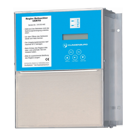
Description of CERTO controller
Standard
Page 2
1. Functions of the controller
Page 4
2. Terminal connection
Page 6
3. Menu structure overview
Page 8
4. Menu structure
Page 9
5. Menu navigation
Page 11
6. Manual mode / external control / humidity control
Page 13
7. Factory-set default settings on the controller
Page 22
8. Fault and error messages
Page 26
9. Operating messages
Page 23
10. Safety and warning notices
E N E R G Y
R E C O V E R Y
Advertisement
Table of Contents

Related Manuals for Klingenburg CERTO


Summary of Contents for Klingenburg CERTO
- Page 1 Description of CERTO controller Standard E N E R G Y R E C O V E R Y Page 2 1. Functions of the controller Page 4 2. Terminal connection Page 6 3. Menu structure overview Page 8 4. Menu structure Page 9 5.
-
Page 2: Functions Of The Controller
1. Functions of the controller The following control units are available depending on the pumping capacity: CERTO FU 750 = 750 Watt CERTO FU 1500 = 1500 Watt Special features: the control units can be used worldwide we have followed all the guidelines available to us in... - Page 3 most modern processor technology thermal contact monitoring includ- CE approved ing function display housing IP 54 Status message short-circuit-proof output Service indicator EN 55011 tested Start-up and run-out circuit EN 61000-3 tested Menu-guided programming EN 61000-4-2 tested Plain text display via LCD display EN 61000-4-3 (burst) tested Three-button operation EN 61000-4-4 (surge) tested...
- Page 4 Control signal 4-20 mA Maximum relay load 250 V AC 1A 0-10 V Follow-up Status Overpressure Maintenance Fault message message message drying run message 8 9 10 11 12 15 16 closed during operation.S2 Wiring of pump station - control unit and S3 closed case Solenoid...
- Page 5 Terminal connections Control unit: 5: Water treatment (+) 6: Water treatment (-) Water 7: +10 V processing 8: Controller signal input (+) 9: Controller signal earth (-) 10: Earth 11: Controller enable (+) 12: Controller enable (-) 13: Low pressure switch D1 (+) 14: Low pressure switch D1 (-) 15: High pressure switch D2 (+) 16: High pressure switch D2 (-)
- Page 6 Start Stop Enter | Return Select up Select down Setting the clock Maintenance Manual draining German, French, Language English, Dutch Codeeinput Operating Mode Manual Humidity Mode control External drive Humidity target value Manual Target Start Point P-Value Value I-Value...
- Page 7 Rinse interval Rinse duration min. frequency Frequency Drying Drying time max. frequency limit Switch points Autostart Step switch Store 2nd, 3rd, 4th step Service- Service Reset Accelerate time hours Decellerate time Line pressure...
-
Page 8: Menu Structure
4. Menu structure The control unit has a double-line, multi-colour illuminated display and is operated via 5 keys. Only for “on-site” operation - priority Start Stop The menu is accessed by pressing the keys simulta- neously. (Control unit reset): Enter | Return Select up Select down Attention: Error acknowledgement is also carried out via this key combination:... -
Page 9: Menu Navigation
5. Menu navigation Pressing the three keys ( ) will take you to: S e r v i c e S t d T T . M M . J J 1 7 . 0 6 . 1 1 This sets the clock that controls the error log. Pressing , again will open the menu item “Manual draining”. - Page 10 C o d e i n p u t : 0 0 0 0 0 To access the main menu, the code 00111 must be entered. This code request protects against unauthorised access. It is therefore advisable to keep these operating instructions in a safe place. Main menu: Confirming with ( ) takes you to the menu item “Operating mode”...
-
Page 11: Manual Operation
6. Manual operation / external control / humidity control Manual operation If “Manual operation” has been selected, a manual target value between 3 Hz and the factory-set maximum frequency can be specified. The manual target value is set by pressing the selection keys. M a n u a l t a r g . -
Page 12: Humidity Control
Here, the relative humidity the humidifier can achieve is set between 10 % and 95 %. The PI-controller is activated duringhumidity control. This ensures that the set target value remains constant. The Klingenburg humidity sensor is required for this purpose. The gain factor is set here. P - g a i n... - Page 13 7. Factory-set default settings on the control unit All factory-set default settings are now displayed, and each setting must be confirmed by pressing ENTER. No changes should be made. M i n i m a l f r e q . M a x i m a l f r e q .
-
Page 14: Minimum Frequency
Minimum frequency M i n i m a l f r e q . 3 - 2 0 H z 1 0 H z The minimum frequency is factory set. The nozzle pressure should be set at a minimum of 5 bar in any humid- ification situation. -
Page 15: Autostart Function
Autostart function A u t o s t a r t f u n k t . A u t o s t a r t The Start and Stop button under the display screen has priority. The “Autostart on” function puts the control unit in Run mode, when menu navigation is completed and after a control unit reset, i.e. - Page 16 Power-down time D e c e l e r . t i m e 1 - 3 0 s e c 1 0 s The power-down time is factory set. In contrast to the power-up time, this is the time required for the motor to get from maximum speed to zero.
- Page 17 Rinse interval W a s h . i n t e r v a l 1 - 9 6 h 4 8 h To ensure hygienic operation of the humidifier, the control unit has an automatic rinsing cycle as standard. The rinse interval is preset at the factory for 48 hours.
- Page 18 Drying run T r o c k n u n g s f u n k t D r y i n g t i m e D r y i n g 1 5 - 1 2 0 m i n 3 0 m i n The control unit is equipped with a delayed shut-off control for drying the humidifier.
- Page 19 S t e p s w i t c h 2 n d S t a g e S t e p s 0 - 8 7 H z 3 0 H z Up to 3 levels can be switched. 2 n d S t a g e o f f...
-
Page 20: Saving The Settings
Saving the settings The changes made must now be saved. This is necessary in S t o r e d a t a ? order to start the control unit in the selected mode. Pressing the Enter key ( ) saves the values. S t o r e d ! If the changes should not be saved, the action can be can- N o t... -
Page 21: Water Treatment
Water treatment The CERTO control unit has a relay contact for water treatment. Closing (potential-free) the control terminals 5 and 6, shuts down the water treatment contact and allows a short time in which to dispense an additive into the... -
Page 22: Fault And Error Messages
8. Fault and error messages 8.1 Controller disabled When this message appears in the display, the control unit is C o n t r . b l o c k e d ! externally disabled via terminals 11 and 12. That is to say, the I s t f r e q . - Page 23 This saved frequency is stored as the maximum frequen- cy until the fault has been rectified or the control unit has been reset. Since the Klingenburg humidifier continues to operate and the nominal frequency is thus also shown in the display, an overpressure fault is displayed.
-
Page 24: Motor Overheating
8.4 Motor overheating M o t o r t e m p ! I s t f r e q . : 0 0 H z The motor in the pump station is protected against damage from overheating. A thermal contact inside the motor sends a signal to the control unit, causing the motor to switch off and triggering a fault message. - Page 25 If the humidifier does not start, you should check the following: Line pressure Control signal Controller enable Power supply When all the conditions are met and the humidifier is still not working, please contact the customer service of Klingenburg GmbH.
-
Page 26: Communication Error
If the message still remains, please contact the customer service of Klingenburg GmbH. 8.8 Software update The special design of the control unit allows the software to be updated at any time. - Page 27 - Ü Status display of the 10 relays A“+” in front of the letter equals: “Relay output connected” A “-” in front of the letter equals: “Relay output open” Status message Main valve intake Overpressure message 2nd level Ü Maintenance message 3rd level Follow-up drying run 4th level...
- Page 28 Control unit type CERTO-FU 750 CERTO-FU 1500 Output 0,75 kW 1,5 kW Protection 10 A delayed fuse (5 x 20 mm) internal 16 A delayed fuse required (external) Mains voltage 220-240 Volt / 50-60 Hz 1~ Weight 3500 g 8000 g Ambient temperature from -10°C to +40°C...
- Page 29 You can enter your settings here: Manual target value Start point Humidity target value Min. frequency Max. frequency Power-up time Braking time Purge interval Purge duration Control factor Drying Level 2 on Level 2 off...
-
Page 30: Safety And Precautions
7. Safety and precautions Before installation and initial operation of the frequency converter, please read through the product handbook carefully and observe all warnings and safety precautions. Make sure that the product manual is easily reachable in the area of the frequency converter. - Page 31 For this reason, Klingenburg GmbH reserves the right to make such changes without prior notice. Despite the careful creation of these instructions, Klingenburg GmbH cannot be held liable for errors or damage which arise from use of this manual.
- Page 32 E N E R G Y R E C O V E R Y Klingenburg GmbH Boystraße 115 45968 Gladbeck, Germany Phone: +49-20 43-96 36-0 Fax: +49-20 43-7 23 62 E-mail: klingenburg@klingenburg.de www.klingenburg.de...
Need help?
Do you have a question about the CERTO and is the answer not in the manual?
Questions and answers