Advertisement
Quick Links
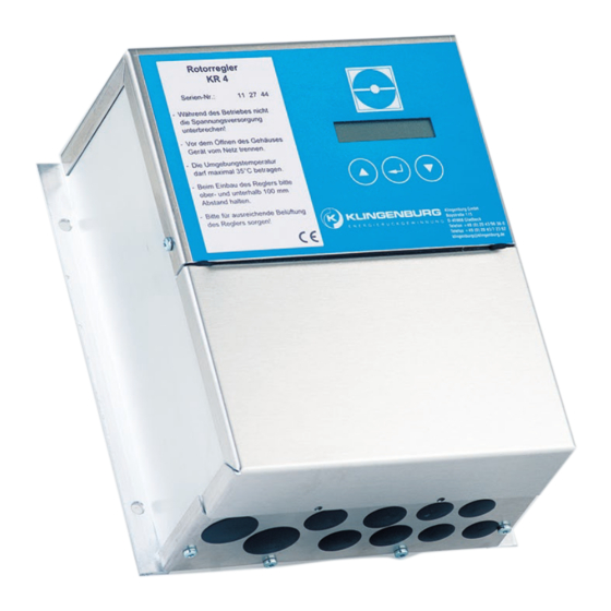
Brief description of KR 4 and KR 7 controllers
Page 2
1. Function of the controller
Page 4
2. Terminal connections
Page 5
3. Technical data
Page 6
4. Initial operation
Page 7
5. Manual mode / external mode
Page 10
6. Trouble-shooting and fault messages
Page 14
7. Safety and precautions
E N E R G Y
R E C O V
1
Advertisement

Related Manuals for Klingenburg KR 4


Summary of Contents for Klingenburg KR 4
- Page 1 Brief description of KR 4 and KR 7 controllers E N E R G Y R E C O V Page 2 1. Function of the controller Page 4 2. Terminal connections Page 5 3. Technical data Page 6 4. Initial operation Page 7 5.
-
Page 2: Function Of The Controller
1. Function of the controller most modern processor technology detailed fault message CE tested thermal contact monitoring housing IP 54 two-line, colourful display lit by LCD We have only two controllers for all rotor sizes: short-circuit proof outlet operating message KR4 = 400 Watt –... -
Page 3: Technical Data
2. Terminals at the control units KR 4 / KR7 3. Technical data Controller typ There is a supply voltage of 24 Volt on the contacts Output 0,4 kW 0,75 kW 5, 7, 9 (and optional 14) Fuse (internal) 6,3 A delay (5 x 20 mm) - Page 4 4. Initial operation of the KR4 / KR7 base controller Navigating through the menu items You can choose between English and German. Other menu languages are available upon request. The change The KR controller is operated with only three buttons. The selection is made with the left ( ) and the right is made by activating the selection button buttons (...
- Page 5 (10 volt =); adjustable in the range of 50 -120 Hz At maximum frequency the rotor must turn at approx. 10 rpm. The maximum rpm adjusts itself according to the type of drive unit. Caution! All motors from Klingenburg are M a n .
- Page 6 The following image appears in the display in manual mode: If the following image should appear instead: H a r d w a r e e r r o r : M a n . f r e q . : 8 0 H z 0 1 ! A c t .
- Page 7 R u n c o n t r o l Overvoltage (motor / rotor blocked, short circuit between U, V, W) e r r o r Overload (controller / motor overloaded) For operation with run control: For operation without run control: Mains under voltage Space from proximity switch to rotor Change the controller programming...
-
Page 8: Safety And Precautions
The provisions of VDE 0160 should be observed as protective measures. Despite the careful creation of these instructions, Klingenburg GmbH cannot be held liable for errors or damage which arise Ground the frequency converter to the connection provided for it. - Page 9 E N E R G Y R E C O V E R Y Klingenburg GmbH Boystraße 115 45968 Gladbeck Germany Tel.: +49-20 43-96 36-0 Fax: +49-20 43-7 23 62 E-mail: klingenburg@klingenburg.de www.klingenburg.de...
Need help?
Do you have a question about the KR 4 and is the answer not in the manual?
Questions and answers