Table of Contents
Advertisement
Advertisement
Table of Contents

Related Manuals for MATO MTS600 Series


Summary of Contents for MATO MTS600 Series
- Page 1 MATO MTS600 series ELECTRONIC TOTAL STATION INSTRUCTION MANUAL...
- Page 2 MTS600 Instruction Manual Preface Thank you for selecting the MTS-600 Electronic Total Station. For the best performance of the instrument, please read this manual carefully and keep it in a convenient location for future reference. Some of the diagrams shown in this manual may be simplified for easier reading.
-
Page 3: Table Of Contents
MTS600 Instruction Manual CONTENTS PRECAUTIONS FOR SAFE OPERATION PRECAUTIONS 1. NOMENCLATURE AND FUNCTION Parts of the instrument Take out the instrument from the case and put it back Using the battery 2. Basic key operation and display Screen and keyboard Operation key Method of inputting numerals and alphabets Preparation for measurement... - Page 4 MTS600 Instruction Manual Data communication Settings of communication Send JOB data Receive known point coordinate data Application program Resection measurements Offset measurement Missing line measurements Remote elevation measurement Area calculation 10. Setting parameters of instrument 10.1 Items set and options 10.2 Operation of setting parameters 10.3 Define function of the USER key Checks and adjustments...
-
Page 5: Precautions For Safe Operation
MTS600 Instruction Manual PRECAUTIONS FOR SAFE OPERATION General l Do not use the unit in areas exposed to high amounts of dust or ash, in areas where there is inadequate ventilation, or near combustible materials. An explosion could occur. l Do not perform disassembly or rebuilding. Fire, electric shock or burns could result. - Page 6 MTS600 Instruction Manual Tripod l When mounting the instrument to the tripod, tighten the centering screw securely. Failure to tighten the screw properly could result in the instrument falling off the tripod, causing injury. l Tighten securely the leg fixing screws of the tripod on which the instrument is mounted.
-
Page 7: Precautions
MTS600 Instruction Manual PRECAUTIONS Precautions Concerning Water And Dust Resistance l Do not put the instrument in the water. The instrument conforms to IPX4, so the normal rain can not damage to the instrument. l Be sure to close the battery cover and correctly attach the connector caps to protect the instrument from moisture and dust particles. -
Page 8: 1. Nomenclature And Function
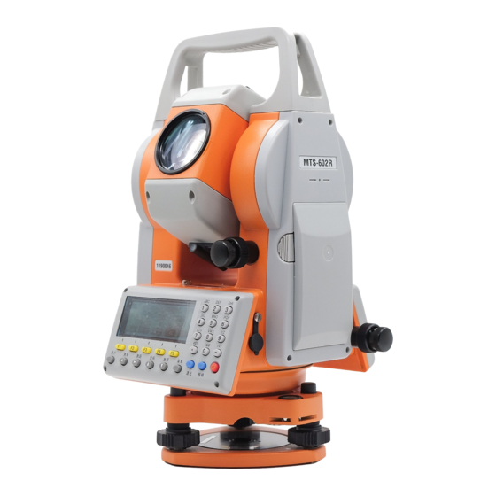
MTS600 Instruction Manual 1. Nomenclature and function 1.1 Parts of the instrument Carrying handle Sighting collimator Telescope grip Telescope eyepiece Battery Plate level Vertical motion clamp Tribrach fixing lever Base Handle fixing screw Objective lens Instrument center mark Communication port Operation keys Horizontal... -
Page 9: Take Out The Instrument From The Case And Put It Back
MTS600 Instruction Manual 1.2 Take out the instrument from the case and put it back. Take out the instrument from the carrying case ① Lays down the instrument carrying case with lid up. ② Unlock the case and open it. ③... - Page 10 MTS600 Instruction Manual ②Plug the charger into the wall outlet. then charging will start, the red lamp will blink. ③When charging finished ,the lamp light turns to green. Unplug the charger and then remove the battery from the charger. 1.3.3 Charger operation manual l Never use this charger with other batteries.
-
Page 11: 2. Basic Key Operation And Display
MTS600 Instruction Manual 2. Basic key operation and display 2.1 Screen and keyboard 2.2 Operation key Function Press this key to turn power on ,press and hold it to turn power off. Cancel the input data or return to the previous screen. LCD lighting switch.( press and hold it to turn on laser plummet) Select the function matching the soft keys. -
Page 12: Method Of Inputting Numerals And Alphabets
MTS600 Instruction Manual 2.3 Method of inputting numerals and alphabets Inputting alphabets Example: Record the station data, input the point as “STN”. PT# : CODE: Ins.ht(m): 1.25 123/ABC JOB VIEW ① Press<123/ABC>,switch to inputting alphabets mode, A would display on right side of screen. - Page 13 MTS600 Instruction Manual PT# : CODE: Ins.ht (m): 1.45 123/ABC JOB VIEW Pressing [ ] can delete the character before cursor. When the cursor located at the first place of the frame, pressing [ ]can delete all the character in frame. Pressing [ ] can move cursor to character to you want to amend, input again.
-
Page 14: Preparation For Measurement
MTS600 Instruction Manual 3. Preparation for measurement 3.1 Setting up the instrument and the tripod ① Adjust the tripod legs so that a height suitable for observation is obtained, make sure the legs are spaced at equal intervals and the tripod head is as level as possible. -
Page 15: Focusing And Target Sighting
MTS600 Instruction Manual 3.2.2 Leveling the instrument with the plate level: ①Loosen the horizontal clamp to turn the upper part of the instrument until the plate level is parallel to a line between leveling foot screws A and B. Center the air bubble using foot screw C leveling foot screws A and B. -
Page 16: Power On/Off
MTS600 Instruction Manual the reticle. The last adjustment of each fine motion screw should be in the clockwise direction. ④ Readjust the focus until there is no parallax: readjust the focus with the focusing ring until there is no parallax between the target image and the reticle. -
Page 17: Tilt Angle Display And Compensation
MTS600 Instruction Manual 3.5 Tilt angle display and compensation MTS-600 has a tilt compensator,it can compensate the error that cause by tilt of vertical axis. The following explains how to check the tilt angle value and turn on/off compensation function. ①... -
Page 18: 4. Basic Measurement
MTS600 Instruction Manual 4. Basic measurement Basic measurement includes angle measurement, distance measurement, coordinate measurement. 4.1 Angle measurement Before the measurement, please inspect once more and make sure the instrument is leveled and centered precisely. After power on, press [ANG] key on the panel to enter V.ang(Z) 92°24′18″... - Page 19 MTS600 Instruction Manual 4.1.2 Horizontal angle setting The horizontal angle can be set to any required angle Setting a horizontal angle from the keys ①Collimate the target and press [HSET] in the first H.angle set H.ang(R): page of the angel measurement mode. ②Enter the horizontal angle value you wish to set.
- Page 20 MTS600 Instruction Manual ③ Collimate the target, and then press [REL] to set V.ang(Z) 92°55′39″ the target angle to the required value. H.ang(R) 90°15′00″ HOLD REP TILT OUTP >> 4.1.3 Selecting the direction of horizontal angle You can select horizontal angle displayed in right angle mode (increasing clockwise)or left angle mode(increasing counterclockwise).
- Page 21 MTS600 Instruction Manual 4.1.5 Horizontal angle repetition To find the horizontal angle with greater precision, perform repetition measurement. 2nd Target(FS) 1st Target(BS) 3rd meas.end(average of three measurements is displayed) 3rd meas.Starts 2nd meas.end(average of two measurements is displayed) 2nd meas.Starts 1st meas.Starts 1st meas.end(the angle is displayed) Instrument Station...
-
Page 22: Distance Measurement
MTS600 Instruction Manual press [ESC]. l The maximum times of angle measurements that can be made is 10. 4.1.6 Outputting angle measurement data MTS-600 can output the angle measurement data to the peripheral equipment such as a computer .Before carrying out this function, you should connect MTS-600 and the peripheral equipment using the serial communication cable, and set communication parameters correctly. - Page 23 MTS600 Instruction Manual and perform an atmospheric correction. MTS measures the distance with a beam of light, but the velocity of this light varies according to the index of refraction of light in the atmosphere. This index of refraction of light varies according to the temperature and pressure. In the normal conditions, with constant pressure, a temperature change of 1℃, or with constant temperature, a pressure change of 3.6hPa,an index change of 1ppm .
- Page 24 MTS600 Instruction Manual pressure are set to the default values. l When ppm value entered directly, temperature and pressure values will be cleared. Prism constant correction value Reflective prisms each have their prism constant(PC). Before measurement, you must set the prism constant correction value of the prism you are using. This instrument’s prism constant correction value has been set to “-30”...
- Page 25 MTS600 Instruction Manual mode is set, the instrument measures the distance as the setting times and the average distance will be displayed. The number of measuring times can be defined by the user. Example 1: Set distance measuring mode as Tracking Dist.Meas.Mode <1/2>...
- Page 26 MTS600 Instruction Manual NOTE: l In short distance measurement, even though the center of the reflective prism and the reticle are slightly misaligned, “*” will be also displayed, but in fact, accurate measurement is impossible. Therefore make sure that the target is sighted correctly.
- Page 27 MTS600 Instruction Manual 4.2.4 Distance measurements display switch In the distance measure mode, the display can be shown in the following three combination. (1) horizontal distance ,vertical angle, horizontal angle (2) horizontal distance, height difference, horizontal angle (3) slope distance, vertical angle, horizontal angle ①In the distance measurement mode, press [DISP] to H.dist 165.274m...
-
Page 28: Coordinate Measurement
MTS600 Instruction Manual 4.3 Coordinate measurement By measuring the angle and the distance of target point, MTS-600 can get the three-dimensional coordinates of the target points (N, E, Z). After power on, press [COORD] key on panel to enter Crd. N the coordinate measurement mode. - Page 29 MTS600 Instruction Manual ② Press F1 to select entering station data N0(m):0.000 ③ Input the station coordinates, press [OK] E0(m):0.000 Z0(m):0.000 If only measuring plain coordinates of target READ point, Z0 may not be input. ④ Input the instrument height, press [OK] to Station data Ins.ht(m):0.000 complete setting up the station .
- Page 30 MTS600 Instruction Manual mode PT-001(CRD) PT-002(CRD) l Press [LIST] to list all point data in the selected PT-003(DIS) ↓ file and search for the required point. 1X>> TOP LAST SRCH OK Method of operating list: l Press [▲] [▼] to move the cursor up and down from line to line; l [F1]([1X>>])is a speed-up key,it can be set that when pressing [▲] [▼] , cursor moves according to a line, one page, two pages, or three pages.(key caption 3X>>,6X>>,9X>>...
- Page 31 MTS600 Instruction Manual Inputting the direction angle ①In <Select Orient.Method> menu , press [F1] to Input BS Direc.Angle select “Input BS direc.ang.” ,then input the direction H.ang(R):145.0238 angle of the backsight point and press [OK]. ②Collimate the backsight point accurately, press Direc.ang=124°34′16″...
- Page 32 MTS600 Instruction Manual (3) Inputting the height of prism If you wish to measure the Z coordinate of target point, Coordinate Meas. the height of the prism must be entered. Psm.ht(m):0.000 In < Coord.Meas./Setup> menu, press [F3] to select"Prism height".Input the height of the prism used, then press [OK].
- Page 33 MTS600 Instruction Manual l The atmosphere correction and the prism constant are set correctly. l Setting up station completed. Prism center is already collimated and returned signal strength is suitable. Psm.const. Press [MEAS] in the coordinate measurement mode, Atmos.crn. 0ppm or press [COORD] key on the panel to start Meas.mode Fine R...
-
Page 34: Setting-Out Measurement
MTS600 Instruction Manual 5. Setting-out measurement Setting-out measurement is used to set out the required point. The difference between the previously input data to the instrument (the setting-out data) and the measured value can be displayed by measuring the horizontal angle, distance or coordinates of the sighted point. - Page 35 MTS600 Instruction Manual ③Input the horizontal distance from the instrument dHA -2°55′39″ → station to the position to be set out and the H.ang(R) 90°15′00″ included angle between the reference and the point MODE EDM HSET MEAS to be set out, then press [OK] l if no input in the angle input line, the system namely takes setting-out angle by the instrument current horizontal angle.
-
Page 36: Coordinates Setting-Out
MTS600 Instruction Manual l When repeat measuring mode or tracking measuring mode is used for setting-out, the result will be displayed in real-time while sighting the prism without pressing any key. ⑧Move the prism forward and backward until the 0°00′00″← → horizontal distance difference is 0m. - Page 37 MTS600 Instruction Manual ① In < Select S-O Mode> menu, press [F2] to S-O Coordinate <1/2> select "S-O Coordinate". F1—Station data F2—STN Orientation F3—Start S-O ②In< S-O Coordinate >menu, press [F1] to select "Station data",input the station coordinate and the height of instrument. Please see "4.3 coordinate measurement". l If instrument station has been set up in the previous coordinate survey, this step can be left out.
- Page 38 MTS600 Instruction Manual l Pressing [DIFF]can see the difference between 0°00′00″← → 0.000m ↑↓ the current coordinate and the setting-out -4.723m coordinate. MODE EDM HSET DIFF MEAS ⑦Observe the height difference between the target 0°00′00″← → and the required point which displayed on the third 0.000m ↑↓...
-
Page 39: Data Recording
MTS600 Instruction Manual 6. Data Recording MTS-600 can store the measurement data ( including distance, angle, coordinate ), station point data ,backsight direction angle data in the internal memory of instrument. A total of 50000 points can be stored. After power on, press [MENU] key on the panel to MENU <1/2>... -
Page 40: Set Backsight Direction Angle And Record The Direction Angle Data
MTS600 Instruction Manual ③ Input point number, code, height of the instrument, PT#: STN-1 then press [OK] to store the station data into memory. CODE: l Press [JOB] ,re-select a JOB to store data. Ins.ht(m):1.500 l Press [VIEW] to view data stored in the current 123/ABC JOB VIEW JOB. -
Page 41: Recode Measurement Data
MTS600 Instruction Manual ⑤Press [OK] to finish orientation, return to Direc.ang=124°34′16″ <Recording Data> menu H.ang(R): 54°30′16″ Collimate BS point? REC CHK 6.4 Record measurement data ①Press【F3】in <Recording Data> menu to start measurement and recording data. l Press [DIST] to measure and record distance data. S.dist V.ang(Z) 92°55′39″... -
Page 42: Configuration Of Data Recording
MTS600 Instruction Manual ⑤ Continue measuring next point. S.dist V.ang(Z) 92°55′39″ l Distance data include slope distance, vertical H.ang(R) 90°15′00″ DIST ANG EDM ALL angle, horizontal angle; Coordinate data include N, E, Z coordinates; Angle data include vertical angle, horizontal angle. l Press [ALL] to perform measurement and automatically record the results. -
Page 43: Reviewing The Data In The Current Job
MTS600 Instruction Manual Auto coord.calc ①In the second page of <Recording Data> menu, ○F1-- Off press [F2] to enter the configuration menu. ⊙F2-- On ② Press [F2] to select "Auto coord.calc". ③ Press [F2] to enable the function, then press [ESC] to return. -
Page 44: Measure And Record Data In Basic Measurement Mode By Pressing One Key
MTS600 Instruction Manual 6.7 Measure and record data in basic measurement mode by pressing one key For the convenience of users, there is a [USER] key on the panel of MTS-600, whose function can be defined by user (Please see "10.3 define function of the USER key"), default function is set as "measure and record data"... -
Page 45: Memory Management
MTS600 Instruction Manual 7. Memory management After power on, press [MENU] key on the panel to Memory Manager <1/2> enter the main menu, select "F2- Memory Manager" to F1--JOB enter memory management mode. In this mode, you F2—Known Coord. can perform the function related to JOB and data in F3—CODE instrument's memory. - Page 46 MTS600 Instruction Manual ②Press [F1] to select“VIEW” to display the list of PT-001(Crd) PT-002(Crd) point records stored in the JOB. Type of the record is PT-003(Dis) ↓ indicated in brackets. 1X>> TOP LAST SRCH VIEW Method of operating point record list: l Press [▲] [▼] to move the cursor up and down from line to line;...
- Page 47 MTS600 Instruction Manual MYJOB ②Press [F2] to select the JOB and return back to JOB JOB001 *JOB002 ↓ list. 1X>> TOP LAST SRCH OPTN 7.1.3 Delete a JOB JOB Manager <1/2> ①In the list of JOB, press [▲] [▼] to move cursor to F1-View the JOB you want to delete, and press [OPTN] to enter F2-Select...
-
Page 48: Management Of Known Coord
MTS600 Instruction Manual 7.2 Management of Known Coord "Known Coord" is a special file of MTS-600 that used to store and manage coordinate data of known points, the difference from normal JOB is that it is only used to store known coordinate data, not measurement data. It is suitable to store common coordinate data that often be used, and can be read in by user conveniently in different projects. - Page 49 MTS600 Instruction Manual ①Press [F2] to select “Known Coord” in <Memory Known Coord. F1-Input coord. Manager> menu to enter <Known Coord> menu. F2-List and view F3-Clear ②Press [F2] to select “List and view” ,the list of A-01(kwn) known point of memory is displayed. A-02(kwn) l Method of list operation, please see "7.1.1 A-03(kwn) ↓...
-
Page 50: Code Manager
MTS600 Instruction Manual ③Press [YES] to confirm the operation and all the Known Coord. known point will be deleted. F1-Input coord. F2-List and view F3-Clear 7.3 Code manager Code can be entered in the memory of instrument in advance. When recording instrument station or measurement data, these codes can be recalled and read in. -
Page 51: Display Status Of Memory
MTS600 Instruction Manual ②Press [F2] to select "List", the code list is displayed ROAD on the screen. WALL SERVICE ↓ 1X>> TOP LAST SRCH DEL ③Press [▲] [▼] to move cursor to code you want to ROAD delete ,then press [DEL],the code will be deleted. SERVICE POLE ↓... -
Page 52: Format Memory
MTS600 Instruction Manual 7.5 Format memory Operation of formatting memory will delete all data in memory including all JOBS, Known Coord file and codes, and resume the memory to factory status. Please take care to use this function to avoid loss of useful data. ①Enter the second page of memory manage mode Memory Manager <2/2>... -
Page 53: Data Communication
MTS600 Instruction Manual 8. Data communication The measurement data of JOB stored in memory of Communication instrument can be transferred to a PC, and the known F1-Send data coordinate data also can be transferred from PC to the F2-Receive data F3-Comms. -
Page 54: Send Job Data
MTS600 Instruction Manual ③ Press [F3] to select“4800 bps”. Comms. Setting <1/2> ○F1--1200 bps ○F2--2400 bps ⊙F3--4800 bps ④Press [ESC] to return to <Communication> menu. Communication F1-Send data The baud rate can be set in parameters setting F2-Receive data mode also, please see "10.Setting parameters of F3-Comms. -
Page 55: Receive Known Point Coordinate Data
MTS600 Instruction Manual 8.3 Receive known point coordinate data ① Connect PC and MTS-600 with communication cable, run total station communication program edit coordinate data, then click 【COMMUNICATION】 , 【 SEND】 , set parameter of communication, then click 【OK】. ② Press Comms./Receive Data [F2] select... -
Page 56: Application Program
MTS600 Instruction Manual 9. Application Program MTS-600 provides Setting-out measurement, Offset measurement, Missing line measurement(MLM), Remote elevation measurement(REM), Resection measurement, Area calculation programs for measuring personnel to suit various applications, besides the basic measurement functions(angel measurement, distance measurement, coordinate measurement). The setting-out measurement program has been introduced in the previous chapter. - Page 57 MTS600 Instruction Manual 9.1.1 Calculating the station coordinate by measuring 2 known points ① In <Program> menu ,press [F1] to select N(m): "Resection ". E(m): Resection procedure will prompt "Input known pt1". Z(m): l Press [PT#] to read in registered coordinate data in memory by entering the point number of known point.
- Page 58 MTS600 Instruction Manual measuring the second known point. ⑥When the two known points have been input and Resection measured, the list of the known points is displayed. <*> Known pt1 <*> Known pt2 ADD REOBS Y/N CALC l Press [▲] [▼] to move the cursor up and down and select the known point. l Press [ADD] to add a known point for resection.
- Page 59 MTS600 Instruction Manual ②Press [ADD] to input and measure the other points N(m): in the same way as described above. E(m): Z(m): REC OK ③Repeat the steps until all required known points are Resection <*> Known pt 3↑ input and measured. <*>...
-
Page 60: Offset Measurement
MTS600 Instruction Manual 9.2 Offset measurement Offset measurement is performed in order to find a point where a target cannot be installed directly or to find the distance and angle to a point which cannot be sighted. It is possible to find the distance and angle to a point you wish to measure by installing the target at a location a little distance from the target point and measuring the distance and angle from the surveying point to the offset point. - Page 61 MTS600 Instruction Manual ①In <Program> menu, press [F2] to select “Offset V.ang(Z) 88°40′42″ measurement”, The procedure prompts measuring the H.ang(R) 45°23′07″ offset point first. Meas.offset point l Press [MODE] to select distance measuring MODE EDM CE MEAS mode. l Press [EDM] to check returned signal, set the atmosphere correction and the prism constant, please see“4.2 distance measurement”...
- Page 62 MTS600 Instruction Manual ⑦Input the horizontal distance between the offset >S.dist 165.274m point and target point. >V.ang(Z) 90°15′33″ Press [OK], the distance and angle of the target point >H.ang(R) 140°14′08″ are calculated REC CRD l Press [REC] to record the results. l Press [CRD] to switch the screen display from distance values to coordinates values.
- Page 63 MTS600 Instruction Manual ② Press [F2] to select offset mode as “Angle”. V.ang(Z) 89°40′48″ H.ang(R) 145°26′17″ Procedure will prompt sighting the target point. Collimate target pt? MEAS ③Sight the target point accurately, press [OK], the >S.dist 165.274m >V.ang(Z) 90°15′33″ distance and angle of the target point are calculated. >H.ang(R) 140°14′08″...
-
Page 64: Missing Line Measurements
MTS600 Instruction Manual 9.3 Missing line measurement Missing line measurement(MLM) is used to measure the slope distance, horizontal distance, and horizontal angle to a target from the target which is the reference(starting point) without moving the instrument. l It is possible to change the last measured point to the next starting position. l When measuring the height difference of two or more points, attach the prism to a pole etc. - Page 65 MTS600 Instruction Manual ③ Press [OK] to confirm the measurement result. V.ang(Z) 88°40′42″ The procedure prompts measuring the end point. H.ang(R) 45°23′07″ Measure 2nd point MODE EDM CE MEAS ④When the measurement is complete, slope distance, MLM S.dist 134.186m horizontal distance and height difference between the H.dist 107.532m end point and the starting point are calculated and V.dist...
- Page 66 MTS600 Instruction Manual 9.3.2 Changing the starting point It is possible to change the last measured point to the next starting position. ①Observe the starting position and target following MLM S.dist 134.186m H.dist 107.532m steps 1 to 3 in "9.3.1 Measuring the distance between V.dist 3.179m 2 or more points".
-
Page 67: Remote Elevation Measurement
MTS600 Instruction Manual 9.4 Remote elevation measurement Remote elevation measurement (REM) is used to measure the height to a point where a prism cannot be directly installed such as power lines , bridge and overhead cables, etc.) The height of the target is calculated using the following formula ×cotθ... - Page 68 MTS600 Instruction Manual ②Press [F1] to select "With psm.ht input ". Psm.ht(m):0.000 V.ang(Z) 88°40′42″ ③ Input the prism height and press [OK]. The H.ang(R) 45°23′07″ procedure prompts measuring the prism first. Collimate psm. and meas. l Press [MODE] to select distance measuring MODE EDM CE MEAS mode.
- Page 69 MTS600 Instruction Manual ④Press [OK] to confirm the measurement results. The V.ang(Z) 88°40′42″ H.ang(R) 45°23′07″ procedure prompts collimating the ground point of Cillimate ground pt. the prism. ⑤Collimating the ground point of the prism and press [OK]. The REM measurement is started. Elve 10.215m Sight the object, the height from the ground to the...
-
Page 70: Area Calculation
MTS600 Instruction Manual 9.5 Area calculation This function can calculate the area of polygon land enclosed with three or more points. The coordinates of the point can be specified by measuring, reading in from memory , and entering directly. PT-03 PT-02 PT-04 PT-01... - Page 71 MTS600 Instruction Manual 9.5.1 Calculate area from measuring boundary point ①In the second page of <Program> menu ,press [F2] < > PT-1 Pts.=0 to select "Area calculation". MEAS INPUT ②Sight the first boundary point and press [MEAS] to Crd *N 134.429m 230.332m start measurement.
- Page 72 MTS600 Instruction Manual 9.5.2 Calculate area from input known point coordinate ①In the second page of <Program> menu ,press [F2] < > PT-1 to select "Area calculation". Pts.=0 MEAS INPUT ②Press [INPUT]. N(m): l Press [READ] to read in registered coordinate E(m): data in memory by inputting the number of known Z(m):...
-
Page 73: Setting Parameters Of Instrument
MTS600 Instruction Manual 10. Setting parameters of instrument This section explains how to set parameters of instrument. The changed setting remains until it is changed again, even when the power is cut off. Params Setting <1/6> After power on, press [MENU] key on the panel to F1-Start-up mode enter the main menu of instrument, select "F2- Params F2-Tilt correction... - Page 74 MTS600 Instruction Manual Select dms(360 ° ), gon(400G) or *dms mil(6400M) for angle unit Angle unit Distance unit Select meter or feet for distance unit,. *℃ Select temperature unit in atmosphere Temperature unit correction. ℉ Select air pressure unit in atmosphere *hPa correction.
-
Page 75: Operation Of Setting Parameters
MTS600 Instruction Manual Scale correction MTS-800 can carry out the distance correction of Average Elevation and Projection by setting a scale factor. If there's a need for this correction, the scale factor should be calculated and entered in instrument's memory by user. Please refer to some professional book about surveying for more details. -
Page 76: Define Function Of The User Key
MTS600 Instruction Manual ④Press [ESC] to return. Parama Setting <5/6> F1-Temperature unit F2-Pressure unit F3-Auto power off 10.3 Define function of the USER key For convenience of user, there is a function key named [USER] on panel of MTS-600, user can define the function that often used to the key. After power on, pressing [USER] key directly can enter the function quickly. -
Page 77: Checks And Adjustments
MTS600 Instruction Manual 11. Checks and adjustments The total station is a precision instrument that requires fine adjustments. It must be inspected and adjusted before use so that it always performs accurate measurements. In addition, the instrument should be inspected with special care after it has been stored a long time, transported, or when it may have been damaged by a strong shock. -
Page 78: Reticle
MTS600 Instruction Manual ② Correct the remaining 1/2 amount of the bubble displacement with the leveling screws. ③ Rotate the instrument 180°or 200g around the vertical axis once more and check bubble movement. if the bubble is still displaced, then repeat the adjustment. 11.1.2 Checking and adjusting the circular level ●... -
Page 79: Adjusting The Telescope Axis
MTS600 Instruction Manual Attachment screws Attachment screws Eyepiece ②Loosen all four attachment screws slightly with the accessory screw-driver. (while taking note of the number of the revolutions) make vertical cross-hair coincide with A by turning eyepiece and tighten the four attachment screws. ③... -
Page 80: Optical Plummet
MTS600 Instruction Manual ⑥ Loosen the vertical motion clamp and tangent screw and plunge the instrument 180°or 200g and fix a sight on point C, which should coincide with the previous point B. ⑦ If point B and C do not coincide, adjust in the following order: ●... - Page 81 MTS600 Instruction Manual Adjustment screws 1/2 of displacement ② Next use the leveling screws and coincide the point and center mark. ③ Revolve the instrument 180°or 200g around the vertical axis, and check the center mark. If it is coincided to the point, then further adjustment is not required.
-
Page 82: Vertical Circle Index Error Correction
MTS600 Instruction Manual 11.5 Vertical circle index error correction l Check ① Set up and level instrument carefully, then turn the power on. Accurately collimate a target with a distance of 30m or further in normal telescope setting(Face1), read the vertical angle L. ②... -
Page 83: Tilt Compensator Zero Point Error Check And Adjustment
MTS600 Instruction Manual ⑥Press [OK] to accept the new values for Instr.Adjustment F1-V.ang. index offset correction and return to <Instr. Adjustment > menu. F2-Tile sensor offset F3-Instrument constant ⑦Press [ESC] twice ,return to basic measurement mode. Follow the steps mentioned above, check vertical circle index error again. - Page 84 MTS600 Instruction Manual Instr.Adjustment F1-V.ang. index offset ② Input “1234” and press [OK], enter <Instr. F2-Tile sensor offset Adjustment > menu. F3-Instrument constant ③Press [F2] to select <Tilt sensor offset>. Tilt ang 0°00′12″ H.ang(R) 45°23′07″ <一>Collimate in face 1? ④Accurately collimate a target in Face1, then press Tilt ang 0°00′12″...
-
Page 85: Check The Constant Of Instrument
MTS600 Instruction Manual 11.7 Check the constant of instrument The additive distance constant of the instrument is adjusted accurately before delivery, and seldom deviates. The additive distance constant can be checked using a baseline with a known distance precision. If there is no baseline, perform these checks as follows. - Page 86 MTS600 Instruction Manual Instr.Adjustment ② Input “1234” and press [OK], enter <Instr. F1-V.ang. index offset Adjustment > menu. F2-Tile sensor offset F3-Instrument constant ③Press [F2] to select <Instrument constant>. Instr.Adjustment Instr. Const. (m):0 ④Input the new value, press [OK].A confirmation Instr.Adjustment Modify instr.constant? screen is viewed.
-
Page 87: Maintenance
MTS600 Instruction Manual 12.Maintenance l If the instrument is moistened by the rain, please make it dry immediately. l Always clean the instrument before returning it to the carrying case. Then lens requires special care. First, dust it off with the lens brush to remove tiny particles, then wipe it with the lens paper or clean soft cloth. -
Page 88: Error Message
MTS600 Instruction Manual 13.Error message Message Meaning What to do Over range The instrument is tilted beyond Re-level the instrument or turn the vertical compensation range. off the tilt compensation in the (±3') bad conditions. if the message displays again, repair is required. Invalid: same as The N.E coordinates of backsight Check and reenter the coordinate... -
Page 89: 14. Specifications
MTS600 Instruction Manual 14.Specifications Telescope Aperture: 45mm Magnification: 30× Image: Erect Field of view: 1°30′ Minimum focus: 1.5m Distance Measurement Measuring range: Reflectorless: MTS-602R 200m MTS-605R 200m Reflective sheet: MTS-602R 800m MTS-605R 800m Single prism: MTS-602R --5.0km MTS-602 ----2.0km MTS-605R ---3.0km MTS-605 ----2.0km Three prisms: MTS-602 -----3.0km... - Page 90 MTS600 Instruction Manual Angle measurement Minimum display: 10″/5″/1″ Standard deviation: MTS-602(R)---2″ MTS-605(R)----5″ Measuring time : 0.1sec. ±3′(MTS-602(R) ) Range of compensation : level parameter : Circular level: 8' /2mm Plate level : 30″/2mm Battery Voltage: DC 7.2V Capacity: Nickel hydrogen battery BDC18H: 1.8AH Working duration(20℃): Distance and angle measurement: 4 hours Lithium battery BDC40L: 4.0AH...
Need help?
Do you have a question about the MTS600 Series and is the answer not in the manual?
Questions and answers