Advertisement
Quick Links
Advertisement

Related Manuals for Mosselman iTRONIC


Summary of Contents for Mosselman iTRONIC
- Page 1 Installation Manual BMW M2/M3/M4 S55 Version: 160320...
- Page 2 Installation manual for BWM models: • F8x M2 Competition • F8x • F8x M3 Competition • F8x • F8x M4 Competition • F8x M4 GTS • F8x M4 CS Important note: Premium Fuel (Octane 98 or higher*) is highly recommended for performance increase and reliability! *Octane 93 or higher in Brazil, Canada and The United States...
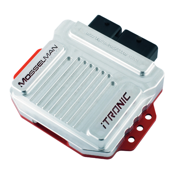
- Page 3 Box Contents • iTronic engine controller • iTronic wiring harness • Installation manual (digital) • Installation hardware Before starting the installation of this product, please read this installation manual carefully to prevent possible damage or injuries.
- Page 4 Table of Contents 1. Preparing for installation 2. Overview 3. Installation 4. Using the iTronic...
- Page 5 Once installation is finished, this makes it easy to confirm visually that all removed parts made their way back into the engine bay. Do not make any changes or modifications to the iTronic Module, including changing the length of the wiring harness.
- Page 6 Overview...
- Page 7 Overview...
- Page 8 Installation 3.1 Remove the windshield covers. • Remove the windshield covers located in fig. 1.1 • 1 & 8: Remove the rivets (fig. 1.2) • 2 t/m 7: Turn the bolts 90º CCW (fig. 1.2)
- Page 9 Installation 3.2 Remove rubber mats. • Remove the rubber mats and connectors located in fig. 2.1, fig. 2.2 and fig. 2.3.
- Page 10 Installation 3.3 Remove the carbon strut brace. • Remove the carbon strut brace located in fig. 3.1.
- Page 11 Installation 3.4 Remove the strut brace. • Remove the strut brace located in fig. 4.1.
- Page 12 Installation 3.5 Remove plastic cover. • Remove the plastic cover located in fig. 5.1.
- Page 13 • Disconnect the connector from the mass airflow sensor. • Attach the mass airflow sensor connector to the iTronic wiring harness. • Connect the connector of the iTronic wiring harness to the mass airflow sensor. 3.7 Mass airflow sensor. • Disconnect the connector from the mass airflow sensor.
- Page 14 • Disconnect the connector from the rail pressure sensor. • Attach the rail pressure sensor connector to the iTronic wiring harness. • Connect the connector of the iTronic wiring harness to the rail pressure sensor. 3.9 Manifold pressure sensor. • Disconnect the connector from the manifold pressure sensor.
- Page 15 • Attach the chargepipe pressure sensor connector to the iTronic wiring harness. • Connect the connector of the iTronic wiring harness to the chargepipe pressure sensor. 3.11 CAN-bus connection - Connector. The necessary CAN wires are located inside wiring loom shown in fig.
- Page 16 (high) and red (low), and should be connected parallel on the existing CAN wires. • Connect the high and low wires from the canbus to the iTronic wiring harness, using the red clip* provided in the box. Shown in fig. 12. • Close the wiring loom.
- Page 17 • Remove the windshield cover to acces the supply voltage. • Remove the round nut of the supply voltage, using a torx. • Connect the red +wire from the iTronic wiring harness. • Replace the round nut on the supply voltage, and tighten sufficiently.
- Page 18 • Connect the two main connectors from the wiring harness to the iTronic. The iTronic is installed. • Secure the iTronic wiring harness using the tyraps provide in the box. Make sure that it can’t reach hot or moving parts. • Reassemble all the covers.
- Page 19 Using the iTronic The iTronic can be controlled, after installing it into the car, with the steering wheel buttons. This chapter will describe how to use all the iTronic.
- Page 20 When the iTronic is turned off the turn signals on your dashboard will light up for 0.5 - 1 second. (fig. 2) Note: When the iTronic is turned off the car will run without any tuning. The iTronic will save the on/off settings when the engine is turned off.
- Page 22 Mosselman Turbo Systems Molenstraat 4 6732 BP, Harskamp The Netherlands +31 (0) 318 457832 info@mosselmanturbo.com www.mosselmanturbo.com /MosselmanTurboSystems @MosselmanTurbo /MosselmanTV...
Need help?
Do you have a question about the iTRONIC and is the answer not in the manual?
Questions and answers