Advertisement
Quick Links
Advertisement

Related Manuals for CHD Elektroservis MXC-200

Summary of Contents for CHD Elektroservis MXC-200
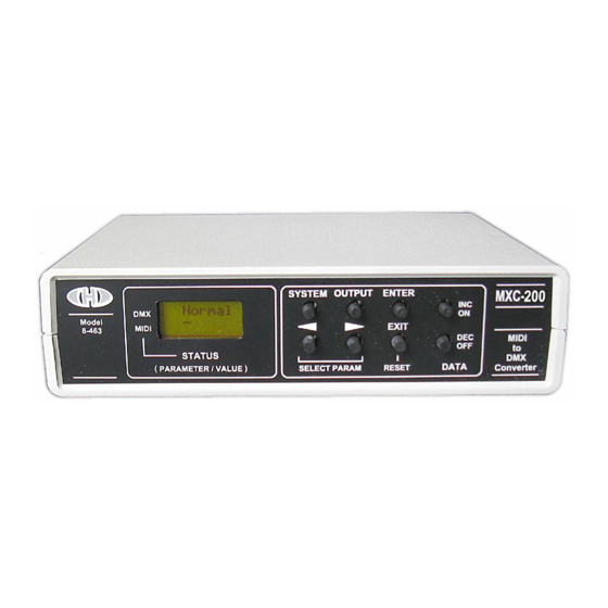
- Page 1 Model 8-463 ver. 1 USER MANUAL © 2017 CHD Elektroservis...
-
Page 2: Table Of Contents
Manufacturer : CHD Elektroservis Nad kundratkou 27, 19000 Praha 9 Czech Republic info@chd-el.cz www.chd-el.cz Copyright © 2017 CHD Elektroservis. All rights reserved. No part of this publication may be reproduced in any form without the written permission of CHD Elektroservis. -
Page 3: Device Description
[11] MIDI-IN connector [12] External foot switches connector [13] DMX-512 output [14] DC Power supply connector Copyright © 2017 CHD Elektroservis. All rights reserved. No part of this publication may be reproduced in any form without the written permission of CHD Elektroservis. -
Page 4: Device Installation
PC, DAW etc. If that function is used, MIDI output MIDI-THRU/OUT of the converter must be Copyright © 2017 CHD Elektroservis. All rights reserved. No part of this publication may be reproduced in any form without the written permission of CHD Elektroservis. -
Page 5: Dmx System Connection
3-pin XLR connectors, the 3-pin connector is used here too for easy interconnection. Pic. 7 - DMX-512 cable wiring variants Copyright © 2017 CHD Elektroservis. All rights reserved. No part of this publication may be reproduced in any form without the written permission of CHD Elektroservis. -
Page 6: External Switches Connection
Pic. 9 – Connection of one external switch 3. DEVICE OPERATION Functional block diagram of the MXC-200 is shown on pic. 10 The signal from the MIDI bus coming in the MIDI input MIDI-IN [11] is supplied to the CPU and back to the MIDI-THRU/OUT [10] output via data merging unit –... -
Page 7: Reset Sequence
Full" switch is ignored in that case. Info about active " Master Full" function is shown on display [1]. 3.3. OPERATING MODES INDICATION Current status of all operating modes of MXC-200 is displayed on the display [1] on the front panel of the device. -
Page 8: Factory Reset
Automatic reset is enabled if an error occurs in MDI communication LCD Contrast Middle level of LCD contrast Copyright © 2017 CHD Elektroservis. All rights reserved. No part of this publication may be reproduced in any form without the written permission of CHD Elektroservis. -
Page 9: Parameters
Copyright © 2017 CHD Elektroservis. All rights reserved. No part of this publication may be reproduced in any form without the written permission of CHD Elektroservis. -
Page 10: System Parameters Setting
MXC-200 ignores new parameter value and continues working with original value of a parameter. Copyright © 2017 CHD Elektroservis. All rights reserved. No part of this publication may be reproduced in any form without the written permission of CHD Elektroservis. -
Page 11: Dmx Channels Used" Parameter
If any of these CCs is received, zero value is sent to all outputs. Copyright © 2017 CHD Elektroservis. All rights reserved. No part of this publication may be reproduced in any form without the written permission of CHD Elektroservis. - Page 12 (outputs) is limited to 128. In “NRPN“ mode, all 200 DMX channels (outputs) are available. Pic. 13 - MIDI SHIFT parameter examples for Notes and CCs Copyright © 2017 CHD Elektroservis. All rights reserved. No part of this publication may be reproduced in any form without the written permission of CHD Elektroservis.
-
Page 13: Midi Shift" Parameter
127 can be chosen or “Blackout " function can be disabled (parameter value ”Dis”). Copyright © 2017 CHD Elektroservis. All rights reserved. No part of this publication may be reproduced in any form without the written permission of CHD Elektroservis. -
Page 14: Midi Rac Cc" Parameter
Output memory bank 1 to 200 (displayed as Content of one selected output memory bank (Out001 to Out200) will be transferred. Copyright © 2017 CHD Elektroservis. All rights reserved. No part of this publication may be reproduced in any form without the written permission of CHD Elektroservis. -
Page 15: Outputs Parameters
MXC-200 ignores new parameter value and continues working with original value of a parameter. Copyright © 2017 CHD Elektroservis. All rights reserved. No part of this publication may be reproduced in any form without the written permission of CHD Elektroservis. -
Page 16: Default Value" Parameter
Pic. 15 – Conversion curve shapes Copyright © 2017 CHD Elektroservis. All rights reserved. No part of this publication may be reproduced in any form without the written permission of CHD Elektroservis. -
Page 17: Preheat" Parameter
DMX output channel. Effect of the "Preheat" parameter on transmitted data shows pic 16. Copyright © 2017 CHD Elektroservis. All rights reserved. No part of this publication may be reproduced in any form without the written permission of CHD Elektroservis. -
Page 18: Limit" Parameter
Exclusive messages. Channel commands are accepted only on MIDI channel selected by the system parameter "MIDI Channel". Copyright © 2017 CHD Elektroservis. All rights reserved. No part of this publication may be reproduced in any form without the written permission of CHD Elektroservis. -
Page 19: Channel Commands
“Note+Aftertouch”. Always when this controller is received (its value must be zero), all outputs are set to minimal value (according to "Preheat" parameter - see chapter 4.2.4). Copyright © 2017 CHD Elektroservis. All rights reserved. No part of this publication may be reproduced in any form without the written permission of CHD Elektroservis. - Page 20 4.2.7). The Blackout function is off for values from 0 to 63 and active for values from 64 to 127 of this Copyright © 2017 CHD Elektroservis. All rights reserved. No part of this publication may be reproduced in any form without the written permission of CHD Elektroservis.
-
Page 21: System Commands
MXC-200 recognizes only the System Reset. Always when System Reset is received, the reset sequence is launched (as well as after switching MXC-200 on - see chapter 3.1 or after manual reset done by EXIT/RESET [8] button). Then the device returns to normal working mode automatically. - Page 22 After that setting of all parameters, the beams will be controlled in accordance with table 9. Copyright © 2017 CHD Elektroservis. All rights reserved. No part of this publication may be reproduced in any form without the written permission of CHD Elektroservis.
-
Page 23: Technical Specification
- mechanical damage caused by customer during transportation or usage of equipment, - unprofessional interference with the equipment or by equipment modification without manufacturer’s approval. Copyright © 2017 CHD Elektroservis. All rights reserved. No part of this publication may be reproduced in any form without the written permission of CHD Elektroservis. -
Page 24: Appendices
Mode 3 : OMNI OFF, POLY Mode 4 : OMNI OFF, MONO X : No Copyright © 2017 CHD Elektroservis. All rights reserved. No part of this publication may be reproduced in any form without the written permission of CHD Elektroservis. -
Page 25: Error Messages
“off” is indicated for each of switches independently. If both switches work properly, continue to next test occurs automatically after about 1,5 sec. Copyright © 2017 CHD Elektroservis. All rights reserved. No part of this publication may be reproduced in any form without the written permission of CHD Elektroservis. - Page 26 MIDI and DMX systems correctly. If any hardware malfunction was detected during testing procedures, the device must be repaired in specialized workshop. Copyright © 2017 CHD Elektroservis. All rights reserved. No part of this publication may be reproduced in any form without the written permission of CHD Elektroservis.
- Page 27 MXC-200 MIDI to DMX-512 Converter Model 8-463 ver. 1 Copyright © 2017 CHD Elektroservis. All rights reserved. No part of this publication may be reproduced in any form without the written permission of CHD Elektroservis.
Need help?
Do you have a question about the MXC-200 and is the answer not in the manual?
Questions and answers