Advertisement
Quick Links
IT
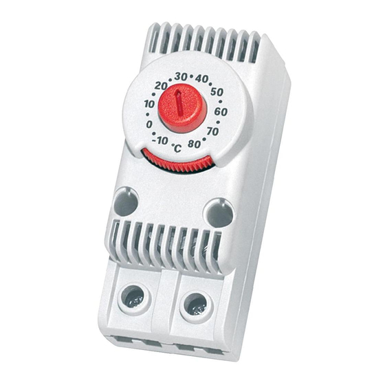
Termostato serie TRT
I N S T A L L A Z I O N E
1
Agganciare il termostato sulla guida utilizzando
gli opportuni ganci elastici.
Se ne ces sa rio è pos si bile bloc care il ter mo sta to
in po si zio ne con due viti UNI 9707-TA 3x20 (non
fornite)
2
Eseguire il collegamento elettrico come descritto
nel paragrafo "Collegamenti elettrici".
3
Regolare la temperatura di set point ruotando
l'apposito disco graduato.
1
AGGANCIO E SGANCIO DALLE GUIDE
Per non danneggiare gli elementi elastici di fissaggio del
termostato, durante le operazioni di montaggio e/o smontaggio
dalle guide, attenersi agli schemi riportati sotto.
AGGANCIO
assembly
rail 32x15mm
(1.26x0.59in)
1
1
1
1
1
1
2
2
2
DIN 46 277/1
EN 50 035
2
2
2
AGGANCIO
2
2
assembly
rail 15x5.5mm
2
2
(0.59x0.22in)
1
1
1
1
DIN 46 277/2
1
1
EN 50 045
1
1
1
COLLEGAMENTI ELETTRICI
1
1
1
Il termostato è fornito di due morsetti a vite per conduttori esterni
flessibili di sezione da 0,75 mm
2
2
2
I morsetti sono adatti ad alloggiare due fili ognuno, per facilitare la
connessione di più apparecchi allo stesso termostato.
2
2
2
1
1
1
Durante la fase di collegamento elettrico attenersi alle seguenti indicazioni:
• utilizzare cavi flessibili adatti per i morsetti in uso
1
1
1
• allentare ciascuna vite del morsetto e inserirvi il conduttore, quindi
serrare le viti. Ad operazione ultimata, tirare leggermente i cavi per
2
2
2
verificare il corretto serraggio
• per serrare le viti, non superare la coppia di serraggio di 0,5 Nm
2
2
2
(0.369 lb·ft)
SCHEMI ELETTRICI
NO
(blu - blue)
+
SGANCIO
FISSAGGIO
disassembly
fixing
1
1
1
1
1
1
2
2
2
2
2
2
SGANCIO
FISSAGGIO
2
2
2
2
disassembly
fixing
2
2
2
2
1
1
1
1
1
1
1
1
1
1
1
1
2
2
2
(AWG18) a 2,5 mm
2
2
2
2
2
1
1
1
1
1
1
2
2
2
2
2
2
Unità di raffreddamento
Cooler
EN
Thermostat TRT series
I N S T A L L A T I O N
1
Hook the thermostat on the rail using the proper
elastic hooks.
Optionally, place the Thermostat in position and
fix with the two UNI 9707-TA 3x20 screws (not
included)
2
Connect the thermostat electrically (see Electrical
Connections).
3
Adjust the set point temperature by rotating the
graduated disc.
2
RAIL MOUNTING
To avoid damage to the elastic fixing elements of the
thermostat, follow the instructions below.
-
-
+
rail 35x7.5mm
(1.38x0.295in)
rail 35x15mm
(1.38x0.59in)
DIN 46 277/3
EN 50 022
ELECTRICAL CONNECTIONS
The thermostat is provided with two screw terminals for external
(AWG13).
conductors
to 2.5 mm
(AWG13).
2
The terminals have capacity for two wires each in order to allow
connection of many devices to the same thermostat.
To connect the thermostat, follow these instructions:
• use flexible conductors suitable for the terminals provided
• loosen each terminal screw and insert the conductor, then
tighten the screws. When finished, pull the conductors gently to
verify if they are tight enough
• to tighten the screws, do not exceed 0.5 Nm (0.369 lb·ft) torque
NC
(rosse - red)
N
L
3
1
1
1
1
1
1
1
1
1
1
2
2
2
2
2
2
2
2
2
2
2
2
2
2
2
2
2
2
2
2
1
1
1
1
1
AGGANCIO
SGANCIO
1
1
1
1
1
assembly
disassembly
1
1
1
1
1
1
1
1
1
1
2
2
2
2
2
2
2
2
2
2
1
1
1
1
1
1
1
1
1
1
2
2
2
2
2
2
2
2
2
2
with
cross-section
from
WIRING DIAGRAMS
Riscaldatore
Heater
-
+
-
+
1
1
2
2
2
2
1
FISSAGGIO
1
fixing
1
1
2
2
1
1
2
2
0.75
mm
(AWG18)
2
N
L
N
L
Advertisement

Related Manuals for Fandis TRT Series

Summary of Contents for Fandis TRT Series
- Page 1 Termostato serie TRT Thermostat TRT series I N S T A L L A T I O N I N S T A L L A Z I O N E Agganciare il termostato sulla guida utilizzando Hook the thermostat on the rail using the proper gli opportuni ganci elastici.
- Page 2 FUNZIONAMENTO OPERATION Il termostato funzione NO (Normally Open - blu), presenta il contatto The NO thermostat (Normally Open - blue) has open contact when aperto quando la temperatura è inferiore a quella di set point e si chiu- the temperature is below the set point value and closes with rising de con la temperatura in aumento.
Need help?
Do you have a question about the TRT Series and is the answer not in the manual?
Questions and answers