Table of Contents
Advertisement
Quick Links
Advertisement
Table of Contents

Related Manuals for Loctite 97115


Summary of Contents for Loctite 97115
- Page 1 EQUIPMENT Operation Manual Loctite Rotorspray ® Part Numbers 97115...
-
Page 2: Table Of Contents
Contents Page No. 1 Please Observe the Following ......... 1-2 1.1 Emphasized Sections . -
Page 3: Please Observe The Following
(1) Rotorspray 97115 (1) Rotor Disc dia. 25 mm (1) Rotor Connection Cord (1) Instruction Manual 97115 (1) Rotor Disc dia. 10 mm (1) Adapter Ring for Diaphragm Valve 97135/97136 As a result of technical development, the illustrations and descriptions in this instruction manual... -
Page 4: For Your Safety
Loctite ® Controller 97123. Low viscosity anaerobic and UV curing adhesives can be applied with the Rotorspray 97115. The rotorspray is not suitable for cyanoacrylate adhesives that are humidity cured and may clog the wetting holes of the rotor disc! -
Page 5: Description
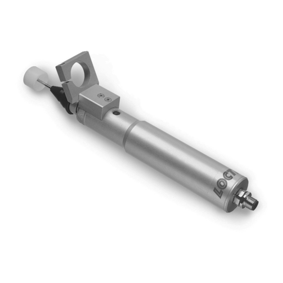
2. Description 2.1 Operating Elements and Connections 1 Rotorspray motor assembly 5 Drive assembly with shaft 2 Rotorspray front end assembly 6 Rotor disc with shaft 3 Access hole 7 Connector For access to the attachment screw 8 Rotor connection cord of the shaft coupling. -
Page 6: Theory Of Operation
2.2 Theory of Operation The Rotorspray 97115 is clamped in a fixture. The stationary applicator is clamped in the holder 4 of the rotorspray so that the tip of the flexible dispensing needle is directed at the inside of the wetting holes on the rotor disc 6. -
Page 7: Technical Data
3. Technical Data Rated speed 8,000 RPM Rated voltage 24 VDC Power consumption 10 W, to 24 W for short periods Operating temperature +10°C to + 40°C (+50°F to +104°F) Storage temperature -10°C to + 60°C (+14°F to +140°F) Weight 0.6 kg Dimensions... -
Page 8: Installation
4. Installation 4.1 Environmental Conditions – Non-condensing humidity – No splashing water 4.2 Assembling the Unit • Clamp the rotorspray into a fixture on the clamping surface. • The holder 4 of the rotorspray must point upward! • Insert the shaft of a rotor disc 6 of the required diameter into the drive assembly 4 to the stop. -
Page 9: Setting Up The Unit
4. Installation (continued) 4.4 Setting Up the Unit 4.4.1 Mounting the Stationary Applicator on the Rotorspray • Loosen the clamping screws of the holder 4 and clamp in the stationary applicator. The tip of the flexible dispensing needle must be placed at a distance of approx. 2 mm from the bottom of the rotor disc 6. -
Page 10: Dispensing
• Purge the stationary applicator of air according to the operating instructions for the stationary applicator. Remove the stationary applicator from the holder for purging. • Perform the filling of the product line according to the operating instructions of the Loctite ® Controller 97123. -
Page 11: Returning To Operation
5. Dispensing (continued) 5.3 Returning to Operation The rotorspray is automatically switched on at the wetting position by the Controller 97123. The dispensing takes place automatically after the rotor reaches the rated speed and according to the preselected dispensing time. Returning to Operation after Longer Periods of Non-use •... -
Page 12: Troubleshooting
(see below). Message in lower line – Controller defect. • Loctite Service. = Channel B Replacement of motor assembly or bearing assembly • Turn drive assembly 5 until the fastening screw of the shaft coupling can be seen in the access hole 3. -
Page 13: Documentation
8 Documentation 8.1 Accessories and Spare Parts Pos. No. Description Loctite Order No. – Rotor Top complete with Shaft Ø 3 mm 97266 Drive Head Assembly 97257 consists of: Rotor Top and Shaft Ø 5 mm Rotor Disc (2 pcs. per box) Rotor Disc, 10 mm dia. -
Page 14: Declarations Of Conformity
EN 50082-1 1992; EN 55014/4 1993; IEC 801-2, 3, 4 Date/Manufacturer´s signature 12/08/2000 General Manager (F. Löhr) For changes to the unit that were not approved by Henkel Loctite, this declaration loses its validity. Declaration of Conformity In accordance with the EC Machine Regulations 98/37/EC The Manufacturer Loctite Deutschland GmbH Arabellastraße 17... -
Page 15: Warranty (Excluding Germany)
A claim of defect in materials or workmanship in any Products shall be allowed only when it is submitted to Henkel Loctite in writing within one month after discovery of the defect or after the time the defect should reasonably have been discovered and in any event, within twelve months after the delivery of the Products to the purchaser. - Page 16 06690-11-Itapevi www.loctite.com Auburn Hills, Michigan 48326 São Paulo-Brazil Loctite is a registered trademark of Henkel Loctite Corporation, U.S.A. © Copyright 2002. Henkel Loctite Corporation. All rights reserved. Data in this operation manual is subject to change without notice. P/N8900422 12/02...
Need help?
Do you have a question about the 97115 and is the answer not in the manual?
Questions and answers