Table of Contents
Advertisement
Quick Links
Advertisement
Table of Contents

Related Manuals for LEM EM4TII+


Summary of Contents for LEM EM4TII+
- Page 1 EM4TII+ Manual 05November2020/V1.0 Page 1/33...
-
Page 2: Table Of Contents
Table of contents Safety instructions and hazard warnings ..................... 3 Product description ..........................4 Installation and connection ........................7 Wall mounting ....................... 7 Electrical connection ..................... 9 Displays and parameterization, data interfaces ................11 Display screen and operating display ................. 11 Parameters and reading out meter data.............. -
Page 3: Safety Instructions And Hazard Warnings
Safety instructions and hazard warnings Please read this chapter through carefully. It familiarises you with the important safety instructions and hazard warnings for handling the EM4TII+ device. CAUTION Do not under any circumstances open the device! Opening the device can cause electric shocks. -
Page 4: Product Description
Product description This operating manual describes all design variants of the EM4TII+. Be aware that meters may be designed differently with regard to configuration, interface, inputs/outputs etc. It is possible that some meter characteristics are described here which do not apply to your meter. The EM4TII+ is a single-phase energy meter as per EN 50463-x:2017 and thus meets the requirements of the EU directive 1302/2014/EU in accordance to Commission Implementing Regulation (EU) 2018/868 and 2019/776. - Page 5 The supply voltage for the EM4TII+ can be selected between 24 V and 110 V as per EN 50155. Two hardware variants are available, one for 24V or 48V, the other one for 72V, 96V or 110V Optionally a communication unit (modem) can be supplied with 12V DC voltage from the EM4TII+. The conditions of use (with regard to EMC, temperature, vibrations etc.) meet the special requirements for locomotives, including the EN 50155, EN 50121-3-2, EN 50124-1 and EN 61373.
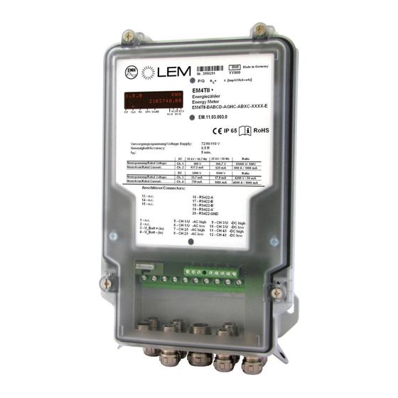
- Page 6 View of the rating plate: Serial number Test LED for active and reactive power LC display Space for ownership marking Specifications on operation of the meter Connection plan and terminal assignment Year + date-code (day of the year) of manufacture Type designation and type code Protection type Adhere to the operating manual...
-
Page 7: Installation And Connection
Installation and connection Wall mounting The EM4TII+ device is designed for three-point mounting as per DIN 43857-2. For a detailed view of the fastening holes see figure 3.1. The four sealing screws for the terminal cover are tightened evenly and alternately to 0.5 Nm with a PZ2. ATTENTION! Damage of the unit due to excessive torque! •... - Page 8 DANGER! Contact of parts under voltage is extremely dangerous! When installing or changing the meter, the conductors to which the meter is connected must be free of voltage. • Remove the relevant back-up fuses and store them in such a way that other people cannot re-insert the back-up fuses without notice.
-
Page 9: Electrical Connection
Electrical connection DANGER! Contact of parts under voltage is extremely dangerous! • Secure meters with a transformer connection in the voltage path with a back-up fuse of <6 A. The supply lines to the device - which can total up to nine depending on the energy meter design - must be laid with cable glands and connected as per figure 3.2. - Page 10 Figure 3.3: Connection assignment (n.c: not connected) Since the nomenclature of the terminals of the RS422 interface for the LEM Products EM4T and EM4TII+ are different, please use in case of replacement of the EM4T with EM4TII+ in an installation the table below to connect the RS422 interface.
-
Page 11: Displays And Parameterization, Data Interfaces
Displays and parameterization, data interfaces Display screen and operating display Figure 4.1: LC display Display of detected mains system on the display screen (possible values): → 16.7 Hz measurement of current on channel 2 (only possible with AC or ACDC version) →... - Page 12 Cursor field: Cursor arrow Function OFF: Reference variable for the LED is active energy Q LED ON: Reference variable for the LED is reactive energy OFF: no GPS telegram received FLASHING: GPS telegram received ON: Valid GPS telegram received -> clock engaged OFF: No communication on the RS232 interface ON: Communication on the RS232 interface OFF: Power reserve for the device clock not depleted...
- Page 13 Duration of the Display Meaning display Display test Appears after commissioning for approximately Energy register for 1 . 8 . 0 k W h positive active energy 0 0 0 0 0 0 0 . 0 0 Energy register for 2 .
-
Page 14: Parameters And Reading Out Meter Data
Parameters and reading out meter data Communication with the EM4TII+ follows the standard IEC 62056-21 (formerly IEC 61107). Knowledge of this standard is assumed for the development of any kind of terminal software dedicated to read the meter data. All data objects are identified here by the OBIS Code System (formerly EDIS code system). OBIS codes are given here in part as a full 6-digit code. -
Page 15: Command And Data Formats
4.2.2 Command and data formats In chapter 4.2.1 an example of a data exchange was given. In the present chapter, all notions related to messages needed for communication will be explained. In chapter 4.2.9 a sample communication cycle with explanations is given to show the use of the messages. Please note: The EM4TII+ interface parameters are: Baud rate:... - Page 16 Programming command message Command sequence SOH C Data set 16 17 Error message Answer f. EM4TII+ E R R ( Error ) ETX Explanations of the parameters in the tables above: Start character „/“ End character „!“ Final characters CR: Carriage return LF: Line feed Acknowledge character (ACK) Start character for the generation of the block test character (BCC, STX = start of text).
- Page 17 Programming command message identification „P“ - Password command „W“ - Write command „R“ - Read command „B“ - Cancel the execution of a command (break) Command type identification (indicates the variant of the command) Values: for the password command „P“ „1“...
-
Page 18: Communication Cycle
4.2.3 Communication cycle To explain the use of the message notions explained in the previous chapter, a communication cycle is given as an example: Request message: /?<xxxxxxxxxx>!<CR><LF> with <xxxxxxxxxxx> = device address (optionally). If no address is specified, any connected meter will answer Acknowledgement/option select message: <ACK>0ZY<CR><LF>... -
Page 19: Access Authorizations
4.2.4 Access authorizations The EM4TII+ user has two access levels via the data interface: • The first level is the password level with read authorisation • The second level is the service level with read and write authorisation The password level enables the user to read data and parameters from the EM4TII+ using the login password. - Page 20 OBIS code Description Write Read Format Remark 0-0:C.1.0*255 Manufacturing number up to 8 digits 0-0:C.72.1*255 Locomotive number W5-password 8-digits ASCII string 0-0:C.72.2*255 Train number W5-password 8-digits ASCII string 1-0:C.1.9*255 Consumption Point-ID W5-password 32-digits ASCII string Note 3) 1-0:0.0.0*255 Identification register 0 W5-password 8-digits ASCII string 1-0:0.0.1*255...
- Page 21 Note 1): Setting of the baud rate of the data interface The setting of the baud rate of the data interface with the above OBIS code must be performed with one of the following parameters: = 300 Baud = 600 Baud = 1200 Baud = 2400 Baud = 4800 Baud...
-
Page 22: Structure Of Load Profile Compilation
4.2.6 Structure of load profile compilation A status word is stored with each load profile record. Each bit in this status word contains information about a certain error or event. Each time an event occurs that changes the status word, a new header with the updated status word is generated and stored. - Page 23 hexadecimal Meaning Usage in load Usage in log profile (P.98) coding *1 depending on configuration AC over voltage 80000000 DC over voltage 40000000 AC under voltage 20000000 DC under voltage 10000000 AC voltage below startup level 08000000 DC voltage below startup level 04000000 AC voltage above U 02000000...
- Page 24 1) Status of the time indication (based on the EBIX system): 3DXXXX invalid time information (in case of failure) or time adjustment within the measurement period to more than two seconds 7FXXXX valid time Note: Time indication status of 38XXXX isn’t supported according to EN50463:2017 anymore.
-
Page 25: Recognition Of The Traction Power System
4.2.7 Recognition of the traction power system The EM4TII+ recognizes the currently applied traction power system. A traction power system is in this sense always understood as a combination of the supply frequency (DC or AC-frequency) and the supply voltage. Rated voltage values (according to EN 50163:2004) of 600V/750V (DC), 1500V (DC), 3000V (DC), 15.000V (16.7 Hz AC), and 25.000V (50Hz AC) can be distinguished. -
Page 26: Error Register (F.f)
On the display of the EM4TII+ a flag signalizes the current supply frequency (DC, 16.7 Hz, 50 Hz or 60 Hz) in the case of a detected traction system. Furthermore, in the billing load profile and in the logbook of EM4TII+ any change of the traction system is stored with the seconds-accurate timestamp. -
Page 27: Examples Of Read-Outs From The Em4Tii
4.2.9 Examples of read-outs from the EM4TII+ The following examples of read-outs illustrate how data and parameters are accessed from the EM4TII+. Note that details in the communication might be realised differently in a specific device. Blue Data to the meter, Green Data back from the meter. - Page 28 4) Reading of the load profile beginning at 03.01.2013 at 11:00 h: /?!<CR><LF> /EMH5\@D4EM4TIIW001--<CR><LF> <ACK>051<CR><LF> <SOH>P0<STX>()<ETX>` <SOH>P1<STX>(00000000)<ETX>a <ACK> <SOH>R5<STX>P.01(1301031100;)<ETX># <STX>P.01(130103110500)(00000000)(5)(9)(C.1.9)()(C.5.1)()(C.5.3)()(0.9.17)()(0.9.18)()(1.29.0)(kWh)(2.29.0) (kWh)(3.29.0)(kvarh)(4.29.0)(kvarh)<CR><LF> (0004916097866601)(7F7F2E)(00)(+00.00000)(+000.00000)(00000.0)(00000.0)(00000.0)(00000.0)<CR><LF> P.01(130103110553)(00000080)(5)(9)(C.1.9)()(C.5.1)()(C.5.3)()(0.9.17)()(0.9.18)()(1.29.0)(kWh)(2.29.0)(kWh) (3.29.0)(kvarh)(4.29.0)(kvarh)<CR><LF> (0004916097866601)(7F7F2E)(00)(+00.00000)(+000.00000)(00000.0)(00000.0)(00000.0)(00000.0)<CR><LF> P.01(130103111000)(00000040)(5)(9)(C.1.9)()(C.5.1)()(C.5.3)()(0.9.17)()(0.9.18)()(1.29.0)(kWh)(2.29.0)(kWh) (3.29.0)(kvarh)(4.29.0)(kvarh)<CR><LF> (0004916097866601)(7F7F2E)(00)(+00.00000)(+000.00000)(00000.0)(00000.0)(00000.0)(00000.0)<CR><LF> P.01(130103111500)(00000000)(5)(9)(C.1.9)()(C.5.1)()(C.5.3)()(0.9.17)()(0.9.18)()(1.29.0)(kWh)(2.29.0)(kWh) (3.29.0)(kvarh)(4.29.0)(kvarh)<CR><LF> (0004916097866601)(7F7F2E)(40)(+00.00000)(+000.00000) (00000.0)(00000.0)(00000.0)(00000.0)<CR><LF> P.01(130103112000)(00000000)(5)(9)(C.1.9)()(C.5.1)()(C.5.3)()(0.9.17)()(0.9.18)()(1.29.0)(kWh)(2.29.0)(kWh) (3.29.0)(kvarh)(4.29.0)(kvarh)<CR><LF> (0004916097866601)(7F7F2E)(40)(+00.00000)(+000.00000)(00005.6)(00000.0)(00001.5)(00000.0)<CR><LF> P.01(130103112500)(00000000)(5)(9)(C.1.9)()(C.5.1)()(C.5.3)()(0.9.17)()(0.9.18)()(1.29.0)(kWh)(2.29.0)(kWh) (3.29.0)(kvarh)(4.29.0)(kvarh)<CR><LF> (0004916097866601)(7F7F7F)(40)(+53.99050)(+009.99670)(00028.1)(00000.0)(00007.5)(00000.0)<CR><LF> P.01(130103113000)(00000000)(5)(9)(C.1.9)()(C.5.1)()(C.5.3)()(0.9.17)()(0.9.18)()(1.29.0)(kWh)(2.29.0)(kWh) (3.29.0)(kvarh)(4.29.0)(kvarh)<CR><LF> (0004916097866601)(7F7F7F)(40)(+53.96860)(+010.01483)(00080.4)(00000.0)(00021.5)(00000.0)<CR><LF>...
-
Page 29: Data Input For Gps Receiver Connection
5) Reading of a single register (1.8.0 as example): /?!<CR><LF> /EMH5\@D4EM4TIIW001--<CR><LF> <ACK>051<CR><LF> <SOH>P0<STX>()<ETX>` <SOH>P1<STX>(00000000)<ETX>a <ACK> <SOH>R5<STX>0:1.8.0()<ETX>^ <STX>0:1.8.0(0955760.30*kWh)<ETX>P <SOH>B0<ETX>q 6) Reading of the time with 0.9.1 command: /?!<CR><LF> /EMH5\@D4EM4TIIW001--<CR><LF> <ACK>051<CR><LF> <SOH>P0<STX>()<ETX>` <SOH>P1<STX>(00000000)<ETX>a <ACK> <SOH>R5<STX>0.9.1()<ETX>_ <STX>0.9.1(104106)<ETX>8 <SOH>B0<ETX>q Data input for GPS receiver connection The EM4TII+ is equipped optionally with a dedicated serial input (RS232 type) to be connected to a GPS receiver system. -
Page 30: Maintenance
Maintenance The meter is maintenance-free. With damages (e.g. caused by transportation or storage) no repairs may be carried out. Once the meter has been opened, all warranty claims cease. This also applies if a defect can be traced back to external influences (e.g. fire, extreme temperature- and weather conditions, incorrect or careless use or treatment). -
Page 31: Measurement
Measurement Measuring principle The load profiles are recorded in datasets at parameterized intervals. The measuring circuit comprises a Sigma Delta ADC for each measuring channel which enables simultaneous capturing of measured values at a sample rate of 4800 Hz. The Sigma Delta method effectively suppresses high-frequency interference on the channels. -
Page 32: Technical Data
Technical data General specifications • 4 galvanic isolated inputs for connection of U- and I-sensors Measuring input channels (either for AC, DC or ACDC), or • for connection of one U-sensor (DC) and up to three I-sensors (DCDCDC) Ranges for rated input values AC: 70 –... -
Page 33: Applied Standards And Regulations
Applied standards and regulations Railway application – EN 50463:2017 Energy measurement on board trains Railway applications – EN 50115:2017 Electronic equipment used on rolling stock EN 50121-3-2: 2016 Railway applications - Electromagnetic compatibility - Part 3-2: Rolling stock – Apparatus EN 61373:2010 Railway applications - Rolling stock equipment - Shock and vibration tests...
Need help?
Do you have a question about the EM4TII+ and is the answer not in the manual?
Questions and answers