
Subscribe to Our Youtube Channel
Related Manuals for Alpha Technologies Cordex CXC HP


Summary of Contents for Alpha Technologies Cordex CXC HP
- Page 1 Cordex HP Controller and I/O Peripherals Hardware Manual Part # 0180036-J0 Effective: 08/2016 Your Power Solutions Partner...
- Page 3 While reasonable efforts have been made in the preparation of this document to assure its accuracy, Alpha Technologies assumes no liability resulting from errors or omissions in this document, or from the use of the information contained herein. Alpha Technologies reserves the right to make changes in the...
-
Page 5: Table Of Contents
ABLE OF ONTENTS ........1 AFETY Safety Wording/Symbols . - Page 6 Front Access ........25 Power System Chassis Ground and DC Ground Reference ..26 Power Inputs .
- Page 7 IST OF IGURES Figure 1: CXC HP Controller ......3 Figure 2: L-ADIO I/O Peripheral .
- Page 8 IST OF ABLES Table 1: Part Numbers and Ordering Options ..... 5 Table 2: Specifications: 3RU Rack Mount CXC HP ....13 Table 3: Specifications: HV-ADIO .
-
Page 9: Safety
Keep it in a safe place. Review the drawings and illustrations contained in this manual before proceeding. If there are any ques- tions regarding the safe installation or operation of this product, contact Alpha Technologies or the nearest Alpha representative. -
Page 10: Battery Safety
• Do not work alone under hazardous conditions. • A licensed electrician is required to install permanently wired equipment. Input voltages can range up to 480VAC Vac. Ensure that the utility power is disconnected and locked out before performing any installation or removal procedure. •... -
Page 11: Introduction
Introduction Scope of the Manual This manual explains the installation and interconnection of Alpha Technologies Cordex™ High Perfor- mance System Controller (CXC HP) and related ADIO peripherals. Rack and DIN rail mounting options are also covered. Overview The CXC HP is an advanced system controller designed for operation with basic or complex power systems. -
Page 12: Part Numbers And Ordering Options
Figure 2: L-ADIO I/O Peripheral Figure 3: 6I-ADIO Figure 4: HV-ADIO Part Numbers and Ordering Options These products and accessories are available to order under the following part numbers. 0180036-J0 Rev E Page 4... - Page 13 Table 1: Part Numbers and Ordering Options (Sheet 1 of 2) Part Number/List Description Option Loose Controllers and Peripherals Standalone CXC HP Controller 0180036-002 Standalone L-ADIO 0180039-002 Standalone Redundant Input Power Module 0180045-001 Standalone 6I-ADIO 0180051-001 HV-ADIO 0180057-001 19/23” 3U Rack Mount Assemblies CXC HP, 19/23”, 3U Rack Mount;...
- Page 14 Table 1: Part Numbers and Ordering Options (Continued) (Sheet 2 of 2) Part Number/List Description Option 1/4" lug, 50' cable 747-028-20-080 3/8" lug, 6' cable 747-082-20-071 3/8" lug, 12' cable 747-082-20-072 3/8" lug, 24' cable 747-082-20-073 3/8" lug, 50' cable 747-082-20-080 CAN Cables, RJ-12 offset to RJ-12 offset, sorted by length 877-176-26...
-
Page 15: Features
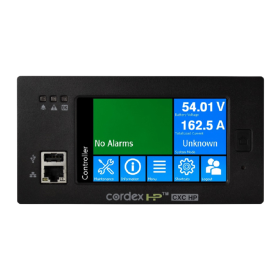
Features CXC HP Controller Figure 5: CXC HP Controller (Left Front View) Figure 6: CXC HP Controller (Right/Top View ) The CXC HP has the following features: • Front touchscreen: full color LCD display, to access controls and menu items by using fingertip touch or a stylus. -
Page 16: Figure 7: Cxc Hp Controller Lcd
• Front panel LEDs: for alarms, progress and status indication.Audio speaker: built-in audio tones during active alarms, and can be disabled if required. • Ethernet: dual ports 10/100 Base T Ethernet connection on both the front and rear of the controller for remote or local communication. -
Page 17: External Peripherals
External Peripherals L-ADIO The L-ADIO is the standard analog and digital I/O peripheral for low voltage (<60Vdc) systems. The L-ADIO communicates on CAN bus to the controller and provides user access to I/O management via the CXC HP controller. Figure 8: L-ADIO I/O Peripheral 4.1.1 Analog Inputs... -
Page 18: Adio
4.1.4 LEDs Each L-ADIO contains three LEDs for peripheral status indication. Color Status Indicator Yellow LVD override engaged Power Blue Power present to the device Comms Green L-ADIO has been acquired by the CXC HP 4.1.5 Front Panel Reset A reset button is located on the front panel for restarting the L-ADIO microprocessor. It takes approxi- mately 15 seconds before the unit is reacquired after pressing the reset button. -
Page 19: Hv Adio
HV ADIO The HV-ADIO is the standard analog and digital I/O peripheral for high voltage (>60 to <300Vdc) systems. The HV-ADIO communicates on CAN bus to the controller and provides user access to I/O management via the CXC HP controller. Figure 10: High Voltage ADIO See the customer connections drawing (xxx-08) at the rear of this manual for additional information on the HV-ADIO. -
Page 20: Redundant Input Power Module
4.3.3 Alarm and Control Output Relays Each L-ADIO contains six Form C alarm output relays to extend alarms and control external apparatus. Each internally generated alarm or control signal may be mapped to any of the six relays, disconnects or other contractors, up to a 50Att maximum load. 4.3.4 LEDs Each HV-ADIO contains two LEDs for Power and Comms status indication. -
Page 21: Specifications
Specifications Specifications: L-ADIO and 6I-ADIO Table 2: Specifications: 3RU Rack Mount CXC HP (Sheet 1 of 4) Cordex Controller Panel/Rack Mount Basic Unit Input Voltage: 12V to 60Vdc within rated limits Electrical Ratings: Controller: 10 to 60Vdc, 1.6A max. L-ADIO: 10 to 60Vdc, 1.6A max. 6I-ADIO: 10 to 60VDC, 0.2A max MTBF: 472,000 @ 25°C (77°F) - Page 22 Table 2: Specifications: 3RU Rack Mount CXC HP (Continued) (Sheet 2 of 4) Cordex Controller Panel/Rack Mount In accordance with FCC requirements, we provide the following statement as specified in the FCC guidelines for conformance to Part 15, Class B: : This equipment has been tested and found to comply with the limits for a Class B digital device, NOTE pursuant to part 15 of the FCC Rules.
- Page 23 Table 2: Specifications: 3RU Rack Mount CXC HP (Continued) (Sheet 3 of 4) Cordex Controller Panel/Rack Mount LED’s: System OK (Green) Power System Minor Alarm (Yellow) Power System Major/Critical Alarm / Controller Fail (Red) Internal Battery: 3V Lithium CR2032 Audio: Built-in speaker for alarm tones Mounting: 3U 19/23”...
- Page 24 Table 2: Specifications: 3RU Rack Mount CXC HP (Continued) (Sheet 4 of 4) Cordex Controller Panel/Rack Mount Weight: 200 grams (0.440 lb.) Voltage Inputs: 4 BiV (-60 to ±60Vdc) Shunt Inputs: 4 (25 to 200Mv) Analog Inputs: 4 DC voltage, 4 DC current, 4 temperature Digital Inputs: 8, plus dedicated LVD override Relay Outputs:...
-
Page 25: Specifications: Hv-Adio
Specifications: HV-ADIO Table 3: Specifications: HV-ADIO (Sheet 1 of 2) HV-ADIO Safety and Certifications IEC\CSA\UL 60950 ICES-003 Class A EN 55022 Class A (CISPR 22) EN 61000-4-2 ESD EN 61000-4-3 Radiated Immunity EN 61000-4-4 EFT /Burst EN 61000-4-5 Surge/Lightning EN 61000-4-6 Conducted Immunity FCC Part 15 Class A, FCC Part 68 In accordance with FCC requirements, we provide the following statement as specified in the FCC guidelines for conformance to Part 15, Class A:... - Page 26 Table 3: Specifications: HV-ADIO (Continued) (Sheet 2 of 2) HV-ADIO Hardware Specifications CPU: Texas Instruments Piccolo LED’s: Communication established (Green), Power (Blue) Mounting: 4 holes on standard CXCHP pitch, optional DIN rail mounting kit Weight: 1 kg (2 lb.) Power Requirements: 90-300VDC 50W 125VDC 0.4A 220VDC 0.2A...
-
Page 27: Mounting Options
Mounting Options The CXC HP controller has been designed as a compact modular controller offering to provide maximum flexibility for various mounting options. Modular, external I/O peripherals allow for additional flexibility with mounting provisions for the entire control system Rack Mount A 3U high panel is available for 19/23"... - Page 28 0180036-J0 Rev E Page 20...
-
Page 29: Inspection
Alpha Technologies is not responsible for damage caused by improper packaging of returned products. If you have any questions before you proceed, call Alpha Technologies: 1 888 462-7487. 0180036-J0 Rev E... - Page 30 0180036-J0 Rev E Page 22...
-
Page 31: Installation
Installation Installation (Low Voltage) This chapter is provided for qualified personnel to install the product. 8.1.1 Safety Precautions : The CXC HP power system is SELV so no shock hazard exists. However, high currents are WARNING possible if IO lines are not correctly fused. The DC output from the rectifiers and the battery system has a high short circuit current capacity that may cause severe burns and electrical arcing. -
Page 32: Shelf Preparation And Mounting
• Network Telecommunication Facilities • Locations where the NEC applies • : A licensed electrician is required to install permanently wired equipment. Input voltages can ATTENTION range up to 300Vdc. Ensure that the all input DC power sources to the equipment are disconnected and locked out before performing any installation or servicing. -
Page 33: Wiring And Connections
Wiring and Connections Safety Precautions This chapter provides cabling details and notes on cable sizing for DC applications with respect to the product. : Hazardous energy levels are present at both the input and the output of power systems. WARNING Ensure that input power and output power is removed before attempting work on the CXC connections. -
Page 34: Power System Chassis Ground And Dc Ground Reference
Figure 14: CXC HP Rack Mount, Panel Folded Down Terminal blocks can accommodate wire sizes specified in section . Route all cables through the access holes, bundle them together with clips and clamp directly into applicable terminal blocks. : Connections to the CXC should comply with all local electrical codes and ordinances NOTE 9.2.1 Tools Required... -
Page 35: Power Inputs
9.3.1 Grounding the Equipment 1. Using 18AWG wire, connect into the PWR1 GND1 connector terminal on the L-ADIO. 2. Run the wire to the PEM stud on the panel. Crimp the wire to a circular lug suitable for 18AWG wire and connect. 3. - Page 36 9.4.1 Redundant Input Power Module (if equipped) 1. Connect system (+) power bus lead to (+) terminal inputs. Three input positions are available (terminals12, 10, 8). 2. Connect system (-) power bus lead to (-) terminals inputs. Three input positions are available (terminals, 11, 9, 7).
-
Page 37: Analog Inputs
9.4.6 L-ADIO - High Voltage 1. Connect 17 on HV-ADIO POUT to terminal 1 on the CXC HP. 2. Connect 16 on HV-ADIO POUT to terminal 2 on the CXC HP. 3. Connect system earth connection to terminal 1. 9.4.7 6I-ADIO - High Voltage 1. -
Page 38: Digital Inputs
Figure 16: Connection Example: Midpoint Monitoring 9.5.2 Ground Fault Detection (HV-ADIO only) V2 is also used for ground fault detection (GFD) (internally connected circuit). Ground fault is detected when either terminal of V2 (system voltage that is normally connected to the battery string) is connected to earth ground either directly or through some conductive means. -
Page 39: Figure 17: Connection Method For +24V Input
Figure 17: Connection Method for +24V input Table 4: Voltage Level Definitions for Digital Inputs Voltage Level (Vdc) Voltage Level (Vdc) Voltage Range (Vdc) Considered as “0”(Off) Considered as “1”(On) 0-60 (system voltage settings) 5V-60V 9.6.2 Connection Method - High Voltage Connect only to un-powered (dry relay) or switch contact rated for low voltages and low current switching. - Page 40 Wiring Connections: L-ADIO : To reduce risk of fire, use only #26 AWG (0.14mm²) or larger wire. CAUTION : To aid the user with installation, frequent reference is made to drawings located at the rear of NOTE this manual. Custom configurations may be detailed within the Alpha power system documentation package.
- Page 41 Table 5: Wiring Connections: L-ADIO (Continued) (Sheet 2 of 2) Terminal Description Signal Type Range 13, 14 and 15; K4 Relay 4 NC / COM / NO 60Vdc / 1A 16, 17 and 18; K5 Relay 5 NC / COM / NO 60Vdc / 1A 19, 20 and 21;...
- Page 42 Table 6: Wiring Connections HV-ADIO (Sheet 1 of 2) Terminal Description Signal Type Range Power Connections 1, 2, and 3; PWR Power Input GND / Neg (-) / Pos (+) 90 to 300Vdc 16 and 17 Power Output Neg (-) / Pos (+) 25 to 55VDC 0.7A Max Analog Inputs 26 and 27;...
-
Page 43: Relay Outputs
Table 6: Wiring Connections HV-ADIO (Continued) (Sheet 2 of 2) Terminal Description Signal Type Range 30 and 31; D4 Digital Input 4 Contact closure detect Open or Short Relay Outputs Terminals 4 to 21, and 64-81 provide 12 Form C contacts (NO, COM and NC) for extending various alarm or control signals. -
Page 44: Network Connection And Remote Communication
9.8.1 Can Serial Port The CXC HP controller has dual CAN bus ports, for communications with Alpha Cordex and AMPS family products and other CAN-enabled equipment on the same system. Connect, via daisy-chain from node to node - use CAN OUT of one node connected to CAN IN of another node, as necessary and ensure that only the last node is terminated. -
Page 45: Maintenance
Maintenance Although very little maintenance is required with Alpha systems, routine checks and adjustments are recommended to ensure optimum system performance. Qualified service personnel should do repairs. The following table lists a few maintenance procedures for this system. These procedures should be performed at least once a year. -
Page 46: Replacing The Lithium Battery
: There are no user serviceable parts inside the CXC HP controller or L-ADIO; the battery is CAUTION removable without tools for replacement. Opening the case will void warranty and could damage sensi- tive electronics inside. 10.2 Replacing the Lithium Battery A removable CR2032 lithium battery is located at the top of the CXC HP controller it is designed to be field replaceable and can be easily removed with no tools. -
Page 47: Warranty And Service Information
Warranty and Service Information 11.1 Technical Support In Canada and the USA, call toll free 1-888-462-7487. Customers outside Canada and the USA, call +1-604-436-5547. 11.2 Warranty Statement For full information details review Alpha's online Warranty Statement at www.alpha.ca. 11.3 Product Warranty Alpha warrants that for a period of two (2) years from the date of shipment its products shall be free from defects under normal authorized use consistent with the product specifications and Alpha’s instructions, the terms of the manual will take precedence.The warranty provides for repairing, replacing or issuing... - Page 48 0180036-J0 Rev E Page 40...
-
Page 49: Certification
Certification CSA (Canadian Standards Association also known as CSA International) was established in 1919 as an independent testing laboratory in Canada. CSA received its recognition as an NRTL (Nationally Recognized Testing Laboratory) in 1992 from OSHA (Occupational Safety and Health Administration) in the United States of America (Docket No. - Page 50 0180036-J0 Rev E Page 42...
-
Page 51: Glossary
Glossary Alternating Current ADIO Analog-digital input-output ALCO Alarm cutoff Asynchronous Transfer Mode; e,g. ATM cell Battery current termination Battery on discharge Battery test (or test mode) Controller Area Network CEMF Counter electro-motive force Cordex series; e.g. CXC for Cordex™ System Controller Direct current Depth of discharge Equalize (mode or voltage) - Page 52 Low voltage alarm Low voltage connect Low voltage disconnect Media Access Control; e.g. MAC address Management Information Base Multiplexer Over Current Protection OLED Organic LED, in-shelf controller display Over-voltage protection Personal Digital Assistant Point to Point Protocol Remote access server SELV Safety Extra Low Voltage Serial Communication Interface...
- Page 56 Canada and USA: 1-888-462-7487 International: +1-604-436-5547 Visit us at www.alpha.ca Due to continuing product development, Alpha Technologies reserves the right to change specifications without notice. Copyright © 2016 Alpha Technologies. All Rights Reserved. Alpha® is a registered trademark of Alpha Technologies.
Need help?
Do you have a question about the Cordex CXC HP and is the answer not in the manual?
Questions and answers