Table of Contents
Advertisement
Quick Links
Advertisement
Table of Contents

Related Manuals for joke ENESKAlaser 1500 mobile

Summary of Contents for joke ENESKAlaser 1500 mobile
- Page 2 LASER welding machines. joke Technology GmbH and its affiliates may not be held liable to the purchaser or third parties for any damages, losses, costs or expenses incurred due to: accidents, improper use or misuse of this product, modifications, unauthorised repairs or alterations carried out on this product, or non-compliance with the operating and maintenance instructions provided by joke Technology GmbH.
- Page 3 In the event that one of our technicians is required to intervene as a result of omissions and/or negligence on the part of the user, the respective expenses will be charged to the customer by joke Technology GmbH. If a fault is detected during the warranty period, joke Technology GmbH will eliminate it, free of charge, in full compliance with the "Warranty conditions".
-
Page 5: Table Of Contents
Precautions for use Technical Specifications How it Works INSTALLATION What's in the Box? Unpacking the Machine ENESKAlaser 1500 mobile Component Diagram Installing Accessories Introducing the Cooling Liquid Positions of Controls Switching on for the First Time SETTING THE MACHINE PARAMETERS... -
Page 6: Asafety
SAFETY... - Page 7 ATTENTION: incorrect implementation of the safety instructions when using the welding machine described in this manual may expose the user to harmful laser radiation. Follow the procedures carefully. disclaims all liability for any damage resulting from a failure to joke Technology GmbH implement the safety instructions provided. SAFETY...
-
Page 8: Absorption Of Laser Radiation
This means that, while ENESKAlaser 1500 mobile radiation is invisible to the human eye, it is close to the threshold of visibility, so that the eye receives it almost in its entirety, but without resulting in a pupillary light refl ex. -
Page 9: Classification And Hazards
The Nominal Ocular Hazard Distance for the is less than 15m in the case ENESKAlaser 1500 mobile of direct or specular ly reflected radiation, and less than 0.5m in the case of diffuse radiation! Only suitable eyewear having an Optical Density (OD) in excess of 4 is capable of protecting the... -
Page 10: General Safety Requirements
RISKS FOR EYES AND SKIN If subjected to intense laser radiation, even for brief periods, or to less intense radiation but for extended periods, both the cornea and the retina may be burnt and damaged irreparably. This is a very real possibility in the case of exposure to a class IV laser beam. -
Page 11: Collateral Risks
COLLATERAL RISKS AND SAFETY SYSTEMS Safety devices must never be removed and must be checked at regular intervals to ensure that they function correctly. If, for example, when using the laser source for its intended purpose, the material undergoes alterations and produces irritating and/or toxic fumes or vapours, it may be necessary to extract and filter the fumes produced by the process before reintroducing them into the environment. -
Page 12: Safety Systems
SAFETY SYSTEMS These systems are listed below, together with a description of how they work: 1. Resonator shutter 2. Microscope shutter 3. Microscope infrared filter 4. Infrared welding filter 1. RESONATOR SHUTTER 2. MICROSCOPE SHUTTER 3. MICROSCOPE INFRARED FILTER Description This device consists of a panel operated by an electro-magnet and located inside the LASER resonator.The shutter interrupts the path of the LASER inside the resonator when the welding machine is in... - Page 13 SAFETY SYSTEMS CONTINUED This filter is an optical glass that is opaque to 1.064 nm wavelength Description LASER radiation. To the human eye, it appears light grey in colour and perfectly transparent. It is located inside the microscope (Ref. A, Figure 3) Purpose The purpose of this filter is to protect the operator’s eyes in the unlikely...
-
Page 14: Safety Labels
The welding system is fi tted with seals at various points. The seals must not be broken or removed for any reason. In fact, the sealed parts may only be opened by joke Technology GmbH personnel. Labels and plates are applied to the equipment in accordance with European safety regulations. These must not be removed or damaged. - Page 15 11. Dangerous to pacemakers. Figure 12 – Radio frequency hazard Hersteller: JOKE Technology GmbH Asselborner Weg 14-16 D-51429 Bergisch Gladbach GERMANY To prevent electrical shocks, do not remove covers. For any service refer only to qualified staff.
- Page 16 If the device generates smoke or unusual odours, unplug the power cable immediately, taking care to avoid burns or other injuries. Continued use of the laser welder in such conditions may result in serious injury and/or damage. The device should only be examined by joke Technology GmbH personnel or its authorised technicians.
- Page 17 Technology GmbH the right to modify information regarding the hardware and software contained in this manual at any time without prior notice.
-
Page 18: Bintroduction
INTRODUCTION... - Page 19 Follow the procedures carefully. NOTE: the system may not be used for any purpose other than that which it has been designed and built for. joke Technology GmbH disclaims all liability for improper use of its products. INTRODUCTION...
-
Page 20: Precautions For Use
(modifying moulds), automotive, arts and crafts. • Do not attempt to weld objects that may contain materials not listed as recommended • Use only joke Technology GmbH parts and consumables. • If you require assistance, contact thejoke Technology GmbH customer service department. •... - Page 21 PRECAUTIONS FOR USE CONTINUED WHAT NOT TO DO • Do not modify the equipment. • Do not attempt to weld objects that contain any of the following materials: beryllium, uranium, plutonium, cadmium, magnesium, sodium, potassium mercury, lead, arsenic... • Do not position combustible materials along the path of the laser beam. •...
-
Page 22: Technical Specifications
TECHNICAL SPECIFICATIONS SPECIFICATIONS DESCRIPTION Power supply VAC Power supply system N. of phases Frequency Hz 50-60 Mean power consumption KW LASER crystal tipo Nd: YAG Wavelength nm 1.064 Pulse energy joule 0,5-200 Pulse duration msec 0,5-20 Repetition frequency Hz 0,5-30 Mean power W Max. -
Page 23: How It Works
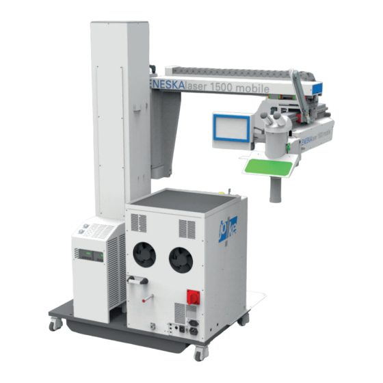
HOW IT WORKS The ENESKAlaser 1500 mobile is a triple-axis laser welding machine that can be positioned as required around significantly sized objects in order to achieve maximum welding precision. The camera installed on the laser binocular allows the operator to monitor the entire welding process precisely and clearly and in real time. -
Page 24: Cinstallation
INSTALLATION... - Page 25 Installing ENESKAlaser 1500 mobile is easy, however it is necessary to observe a series of basic rules. Unpack the machine taking the same care as we did when packing it and get ready for it to be installed. WARNING: when you open the crate and start to unpack the machine, be careful not to damage...
-
Page 26: What's In The Box
WHAT'S IN THE BOX? The box also contains the following accessories, which have been packed separately and must be mounted on the machine: ENESKAlaser 1500 mobile RUBBER TUBE WITH FITTING AND FUNNEL JERRYCAN WITH COOLANT LIQUID WELDING MACHINE JOYSTICK WITH CABLE... -
Page 27: Unpacking The Machine
UNPACKING THE MACHINE Once you have opened the box, start assembling the accessories and begin the initial installation procedure; the machine must be positioned on a flat surface so that it can be moved on its wheels. After removing the wooden packaging panels, remove the wooden retaining blocks using a crosstip screwdriver (figure 14). - Page 28 ENESKAlaser 1500 mobile – Main Components 1. Lockable rotating castors 2. Case 3. Emergency stop push-button and ignition key 4. Y Axis 5. Z Axis 6. Focal extension (laser exit point) 7. Infrared welding filter 8. Binocular 9. X Axis 10.
-
Page 29: Installing Accessories
INSTALLING ACCESSORIES Before starting to install the accessories, make sure that the machine is located in a closed environment with a suitable ventilation system and is isolated from other environments. First of all, it is necessary to install a magnetic sensor on the entrance door to the environment where the welding machine is installed and connect it to the circular interlock socket located on the rear of the machine (figure 16). - Page 30 FILLING THE COOLING LIQUID • Insert the plastic connection supplied with the machine (figure 23) into the female connector at the bottom left of the rear machine panel. • Remove the red cap at the top. • Fill the tank using the funnel provided. •...
-
Page 31: Positions Of Controls
POSITIONS OF CONTROLS Figure 24 – Controls Reference Description Emergency stop mushroom push-button Ignition key Mobile shielding gas diffusor JOYSTICK • Moving the joystick to the LEFT or RIGHT will cause the arm to move along the X AXIS; • Moving the joystick FORWARD or BACK will cause the arm to move along the Y AXIS;... - Page 32 TOUCH SCREEN DISPLAY CONTROLS The touch screen display mounted on the machine may be used to access the various machine functions and set-up the corresponding parameters depending on the type of welding operation. The home screen includes the MENU BAR (highlighted in RED in figure 27) , the INFO MENU, identified by a button bearing the letter "i"...
- Page 33 TOUCH SCREEN DISPLAY CONTROLS CONTINUED • WAVE – graphically displays the LASER pulse waveform in use. You can choose from 5 different waveforms using the buttons positioned next to this box. The default setting is the "normal" or square- shaped waveform. •...
- Page 34 TOUCH SCREEN DISPLAY CONTROLS CONTINUED • CONTACT – press this button to access the contact screen, as shown in figure 30, where it is possible to view the manufacturer's data. • MEMORY SETTING – you can save up to 99 combinations of parameters and use this screen to select one of the saved ones (figure 31).
- Page 35 TOUCH SCREEN DISPLAY CONTROLS CONTINUED KEYBOARD/MEMORY SCREEN Press the "N" button in the HOME screen to access the screen illustrated in fi gure 35. This function may be used to save the current machine parameter settings. Use the text box at the top left to assign the confi guration a name and the red box for the confi guration number.
- Page 36 TOUCH SCREEN DISPLAY CONTROLS CONTINUED CAM SCREEN In the CAM screen it is possible to monitor the point where the machine is centred for welding in real time via the webcam installed on the machine. A red cross is displayed at the centre of the screen (figure 39) representing the laser contact point, behind which appear the images transmitted by the webcam installed on the machine.
- Page 37 TOUCH SCREEN DISPLAY CONTROLS CONTINUED Figure 39 – Cam screen Figure 40 – Cam menu screen Figure 41 – Manuals screen Figure 42 – Language menu screen INSTALLATION...
-
Page 38: Switching On For The First Time
SWITCHING ON FOR THE FIRST TIME After ensuring that you have carried out the instructions on pages 23 and 24 to the letter it is possible to switch the machine on for the fi rst time. • Connect the power cable to the female socket on the rear of the machine, as indicated in Figure 43; •... - Page 39 SWITCHING ON FOR THE FIRST TIME CONTINUED SWITCHING THE MACHINE OFF To switch the machine off, first turn the ignition key to the LOCK position and wait for the message "LASER LOCKED" to appear in the red box on the display. When this message appears, turn the ON/OFF selector switch on the rear of the machine to OFF.
-
Page 40: Setting The Machine Parameters
SETTING THE MACHINE PARAMETERS... - Page 41 The preceding chapters provide all the necessary information about safety, the machine and its accessories, the assembly procedures and initial start-up; the following chapter concentrates on setting the parameters and the actual welding process. ATTENTION: the welding settings provided in this chapter consist of groups of parameters that are specific for the type of material but are not UNIVERSAL.
- Page 42 SETTING THE WELDING PARAMETERS Before starting work, set the POWER, SPOT, TIME, FREQUENCY and WAVE TYPE values, depending on the type of material to be welded. The table in figure 47 lists the default settings for various types of material. These data, which were obtained from laboratory tests on samples of commercially available material, are provided FOR REFERENCE ONLY.
-
Page 43: Axes Speed Settings
SETTING THE AXIS PARAMETERS To set the X, Y, Z and R axes parameters, press the corresponding button on the home screen or the info menu to access the motor controls screen (fi gure 48). Each axis must be set independently of the others. The movement of the axes may only be controlled by the JOYSTICK. -
Page 44: Welding With Eneskalaser 1500 Mobile
WELDING WITH THE ENESKAlaser 1500 mobile... - Page 45 By following a few simple instructions you will be ready to use the ENESKAlaser 1500 mobile and embark on a new welding experience ATTENTION: if you have never welded using laser technology before, we recommend contacting the machine manufacturer, who can organise training courses explaining how to weld using the ENESKAlaser 1500 mobile.
- Page 46 THE PHYSICAL PRINCIPLE OF LASER WELDING The physical principle behind the generation of laser light is the phenomenon of stimulated light emission. In fact, LASER stands for Light Amplification by Stimulated Emission of Radiation. Thus, a laser may be defined as light amplified by the emission of a chain of photons, originating from an initial photon (light particle) that interacts with an excited atomic system and stimulates the emission of two additional photons, which, in turn, interact with other atoms, giving rise to an avalanche effect.
- Page 47 LET'S GET WELDING! Follow these step by step instructions to start welding: 1. Switch on the machine as described in the initial installation procedure, and then rotate the ON/ OFF selector switch on the rear of the machine to the "ON" position. 2.
- Page 48 TROUBLESHOOTING FAULT MAINTENANCE...
-
Page 49: Troubleshooting, Faults And Maintenance
This chapter describes the maintenance procedures and basic issues affecting your ENESKAlaser 1500 mobile. For details and important issues contact customer support. TROUBLESHOOTING, FAULTS AND MAINTENANCE... -
Page 50: Error Messages
ERROR MESSAGES The error messages that may appear on the display are listed in the table in figure 50: ER.No MESSAGE CAUSE REMEDY SIMMER ERROR The Laser lamp does not switch on A. Check the fuse B. Call CUSTOMER SERVICE COOLANT AT The coolant is at stillstand inside A. - Page 51 AXIS ERROR MESSAGES The axis error messages, which are listed below, only appear on the motor control page: 1. MOTOR TEMPERATURE ERROR – this error occurs when the motor reaches the working temperature limit. Wait for the motor to cool down before using the respective axis (fi gure 51). When this error is active, the axis position reset button is replaced by the high temperature warning icon.
-
Page 52: Faults
FAULTS The table in figure 55 presents a list of faults and possible corrective actions. PROBLEM CORRECTIVE ACTIONS The machine switches on but does not assume Check the position of the key Ø the START position. The display indicates the parameters but the Check that the firing pedal is connected to the machine Ø... -
Page 53: Replacing The Ar/Ar Safety Window
REPLACING THE AR/AR SAFETY WINDOW Whenever the protective window is "dirty" the laser power output is reduced.Therefore, when there is a significant concentration of metal spatter on its surface, the glass should be replaced. Check the microscope lens protective window located inside the welding chamber at regular intervals. This special anti-reflective @ 1,064 nm glass is secured to the output of the optical path by means of an aluminium ring nut, which is, in turn, held in place by a screw. - Page 54 ALIGNING THE AIMING SIGHT To adjust the stereo-microscope, unscrew it from its base (Ref. D - Fig. 61), using the 2.5 mm Allen screwdriver provided, and once it has been pushed firmly against the front edge of its base, or in other words away from the operator's position, screw it down firmly so it is immobilised permanently in that position.
-
Page 55: Replacing The Cooling Liquid
REPLACING THE COOLING LIQUID • Insert the plastic connection without the funnel (figure 62) supplied with the machine into the female connector at the bottom of the laser rear panel, figure 63. • Remove the red cap at the top (figure 62) and allow the water to drain completely from the plastic connection, tilting it downwards so that it collects in a suitable recipient. - Page 56 ORDINARY MAINTENANCE The instructions for carrying out ordinary maintenance on the machine mechanical parts are set out below. This type of maintenance is important to preserve the integrity of the parts that determine the precision and movement of the laser. These operations must be carried out at regular intervals since it is important to check the state of wear and tear of the mechanical parts and the integrity of the machine in general periodically.
- Page 57 ORDINARY MAINTENANCE CONTINUED MAINTENANCE ON LINEAR MOTOR STATORS The stators in the linear motors create a magnetic field that attracts metal parts and welding residues, so it is very important that they are always clean and free from any attached particles that could compromise their correct operation.
-
Page 58: Technical Assistance
TECHNICAL ASSISTANCE In the event of technical problems or any other issues, please contact: joke Technology GmbH Asselborner Weg 14 - 16 D-51429 Bergisch-Gladbach TEL. +49 (0) 22 04 / 8 39-0 / FAX +49 (0) 22 04 / 8 39-60 MAIL info@joke.de... -
Page 59: Eec Conformity And Ce Marking
DECLARATION OF COMPLIANCE joke Technology GmbH declares that, provided the conditions specified in this document are satisfied, the ENESKAlaser 1500 mobile source complies with the requirements of the LOW VOLTAGE Community Directives. NOTE FOR THE APPLICATION OF OTHER EEC DIRECTIVES LASER sources are not subject to other EEC Directives, apart from those listed in paragraph 2. -
Page 60: General Safety Requirements During Welding
GENERAL SAFETY REQUIREMENTS DURING WELDING... - Page 61 When it is necessary to evaluate the safety of any given system, the first step is to identify the hazards relating to the operations performed by such a system. GENERAL SAFETY REQUIREMENTS...
-
Page 62: Protection Systems
INTRODUCTION In the event that a LASER Device is installed on the system, in addition to the usual hazards deriving from the system functions and operating modes, it is necessary to bear in mind the additional hazards represented by LASER radiation (electromagnetic radiation, mainly infrared). The safety of this type of equipment is subject to specific standards, both from the electrical point of view and from the point of view of radiation (non-ionised). -
Page 63: Special Requirements
SAFETY The monitoring optics must be equipped with special attenuator devices capable of preventing personnel from accessing radiation levels in excess of class I AEL. This is particularly important in the case of systems fitted with inspection windows for viewing the interaction between the LASER beam and the process material. -
Page 64: Residual Risks
SAFETY RESIDUAL RISKS THAT THE USER MUST IDENTIFY AND ELIMINATE These are risks deriving not from the LASER itself but from its use. In fact, associated with the main radiation, are collateral infrared and ultraviolet radiation, which, due to their intensity, may represent a potential hazard. - Page 65 NOTE...
- Page 66 NOTE...
- Page 67 NOTE...
- Page 68 MAIL info@joke.de www.joke-technology.de © Copyright joke Technology GmbH • April 2019 • All rights reserved for technical changes, inaccuracies and printing errors • All prices plus statutory VAT in . BA2086GB addition to postage and packaging • Reprinting, even in excerpts, only with prior written agreement. • Order No...
Need help?
Do you have a question about the ENESKAlaser 1500 mobile and is the answer not in the manual?
Questions and answers