Table of Contents
Advertisement
Quick Links
Boiler Manual
DO NOT USE BOILER DURING CONSTRUCTION
follow the requirements given on page 9. Failure to comply could result in severe personal injury, death or substantial
property damage.
This manual must only be used by a qualified heating installer/service technician.
instructions, including this manual, and any related supplements. Perform steps in the order given. Failure to comply
could result in severe personal injury, death or substantial property damage.
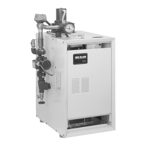
Series 2
Gas-Fired Water Boilers
with Tankless Heater
• Installation
• Startup
unless you provide dust-free air to the boiler area or
Part Number 550-110-290/0219
• Maintenance
• Parts
Before installing
, read all
Part number 550-110-290/0212
Advertisement
Chapters
Table of Contents

Related Manuals for Weil-McLain CGt 2 Series


Summary of Contents for Weil-McLain CGt 2 Series
- Page 1 Series 2 Gas-Fired Water Boilers with Tankless Heater Boiler Manual • Installation • Maintenance • Startup • Parts DO NOT USE BOILER DURING CONSTRUCTION unless you provide dust-free air to the boiler area or follow the requirements given on page 9. Failure to comply could result in severe personal injury, death or substantial property damage.
-
Page 2: How It Works
Boiler Manual GAS-FIRED WATER BOILER — Series 2 — How it works . . . Control module NOTE — The control module provides a pump exercis- The control module responds to signals from the room ing routine. If the boiler is not operated for 30 days, the thermostat, tankless heater low limit, air pressure switch and control module will power the circulator for 30 seconds, boiler limit circuit to operate the boiler circulator, pilot burner,... - Page 3 Boiler Manual GAS-FIRED WATER BOILER — Series 2 — CGt Gas-Fired Water Boiler with tankless heater Actuator 3-way valve connections Connect to supply piping as detail Connect shown to system upper return piping right Connect to circulator as shown 071001 Part Number 550-110-290/0219...
-
Page 4: Table Of Contents
Boiler Manual GAS-FIRED WATER BOILER — Series 2 — Contents How it works ............2–3 Hazard definitions ..........4 Please read before proceeding ....... 5 1 Prepare boiler location ........6–11 2 Prepare boiler ..........12–13 3 Venting ............14-19 4 Water piping ............ -
Page 5: Please Read Before Proceeding
• Do not use petroleum-based cleaning or sealing com- salt residue. Therefore, Weil-McLain equipment contaminated pounds in boiler system. Water seal deterioration will with saltwater or polluted water will no longer be covered under occur, causing leakage between sections. - Page 6 Boiler Manual GAS-FIRED WATER BOILER — Series 2 — Prepare boiler location — codes & checklist Installations must Before locating the boiler, follow these codes: check the following: • Check for nearby connection to: • Local, state, provincial, and national codes, •...
-
Page 7: Prepare Boiler Location
Boiler Manual GAS-FIRED WATER BOILER — Series 2 — Prepare boiler location — clearances Recommended SERVICE clearances Figure 2 Required MINIMUM clearances (Fig. 1) 1. Provide clearances for cleaning and servicing the boiler and for access to controls and components. See Figure 1 for recommen- dations. -
Page 8: Prepare Boiler
After it has been determined that exists for condensation to occur. Condensation remaining connected to the common venting system can damage a masonry chimney. Weil-McLain properly vents when tested as outlined above, return recommends the following to prevent possible doors, windows, exhaust fans, fireplace dampers, and damage. - Page 9 Boiler Manual GAS-FIRED WATER BOILER — Series 2 — Prepare boiler location — contamination Table 1 Please review the following information on potential Refer to for products and areas which may cause combustion air contamination problems. contaminated combustion air. To prevent potential of severe personal injury or death, check for products or areas listed below before installing boiler.
- Page 10 Boiler Manual GAS-FIRED WATER BOILER — Series 2 — Prepare boiler location — air openings Figure 3 Air openings to interior spaces Combustion air opening location and sizing ✷ requirements depend on the clearances around the boiler. ✷ Check the boiler placement compared to Figure 1, page 7.
- Page 11 Boiler Manual GAS-FIRED WATER BOILER — Series 2 — Prepare boiler location — air openings (continued) Unusually tight construction FREE AREA of openings — the minimum areas Unusually tight construction means (per ANSI Z223.1) given in this manual are free area (equals the area, buildings in which: length times width of opening, after deduction for louver obstruction).
- Page 12 Boiler Manual GAS-FIRED WATER BOILER — Series 2 — Prepare boiler — placement and setup Place boiler/crate near Inspect orifices and burners position Correctly-sized manifold orifices must be used. Failure to do so will 1. Leave boiler in crate and on pallet until installation result in severe personal injury, death site is ready.
- Page 13 Boiler Manual GAS-FIRED WATER BOILER — Series 2 — Prepare boiler — pressure test Hydrostatic pressure test 3. When water flows from shutoff valves, close boiler drain valve. Pressure test boiler before attaching water or gas piping 4. Close shutoff valves. (except as noted below) or electrical supply.
-
Page 14: Venting
Boiler Manual GAS-FIRED WATER BOILER — Series 2 — Venting — general information CGt venting options — Chimney draft or Direct exhaust Chimney draft venting Direct exhaust venting (vertical or sidewall) Chimney draft venting uses the natural draft provided Direct exhaust venting uses inside combustion air with by a vertical vent or chimney. - Page 15 Boiler Manual GAS-FIRED WATER BOILER — Series 2 — Venting — direct exhaust — components Obtain vent components 1. The following special gas vent systems comply with 2. Select vent method based on page 14 and installa- UL-1738 and ULC-S636 standards and are certified tion requirements.
- Page 16 Boiler Manual GAS-FIRED WATER BOILER — Series 2 — Venting — direct exhaust — vent starter 1. Select a vent pipe manufacturer and Figure 8 FasNSeal™ vent starter Figure 9 Z-Vent II vent starter obtain all vent components needed, based on boiler location and venting method.
- Page 17 Boiler Manual GAS-FIRED WATER BOILER — Series 2 — Venting — direct exhaust — termination Follow instructions on this page when determining vent 12. Canadian installations — See B149.1 or B149.2 location to avoid possibility of severe personal injury, Installation Code. Terminate vent no less than 6 death or substantial property damage.
- Page 18 • Vent is sloped toward termination as shown in dotted lines in Figure 14. • The vent is installed per Weil-McLain and vent manufacturer’s instructions. Condensate drippage from such vents may accu- mulate on the ground below. Consider traffic in the area to avoid hazard due to ice accumulation.
- Page 19 Boiler Manual GAS-FIRED WATER BOILER — Series 2 — Using any termination other than one of those shown could cause nuisance outages and loss of heat, resulting in substantial property damage. Figure 15 Sidewall termination Part Number 550-110-290/0219...
- Page 20 Boiler Manual GAS-FIRED WATER BOILER — Series 2 — Water piping — general information General piping information The circulator is shipped loose (wiring pre-attached to boiler). Pipe the circulator on the return line only, as If installation is to comply with ASME or Canadian shown on page 3 and page 64.
-
Page 21: Water Piping
Boiler Manual GAS-FIRED WATER BOILER — Series 2 — Water piping — system System water piping Use Figure 16 only for single-zone See Figure 16 and Table 5 for near-boiler piping and systems designed for return water piping for single-zone systems designed for return water at least 130°F. - Page 22 . Instead, provide controls and piping which can regulate the boiler return water temperature at no less than 130°F regardless of system supply temperature. Contact your Weil-McLain representative for suggested piping and control methods. Failure to prevent cold return water temperature to the boiler could cause corrosion damage to the sections or burners, resulting in possible severe personal injury, death or substantial property damage.
- Page 23 Boiler Manual GAS-FIRED WATER BOILER — Series 2 — Water piping — multiple zones (continued) Figure 17 Zoning with circulators Figure 18 Zoning with zone valves — return water 130°F or higher. — return water 130°F or higher. Boiler isolation (balancing) valves Automatic air vent (with diaphragm-type expansion tank), or con- nect to tank fitting (closed-type expansion tank).
- Page 24 130°F regardless of system supply temperature. Contact your Weil-McLain representative for suggested piping and control methods. prevent cold return water temperature Failure to to the boiler could cause corrosion damage to the sections or burners, resulting in possible severe personal injury, death or substantial property damage.
- Page 25 Boiler Manual GAS-FIRED WATER BOILER — Series 2 — Piping — low temperature systems (continued) Figure 19 By-pass piping Figure 20 By-pass piping Zoning with circulators Zoning with zone valves Boiler isolation (balancing) valves Blend temperature gauge Flow/check valve Relief valve System or zone circulator Automatic air vent System temperature gauges...
- Page 26 Boiler Manual GAS-FIRED WATER BOILER — Series 2 — Water piping — connect tankless heater Hot Water Can Scald! • Consumer Product Safety Commission and some states recommend domestic hot water temperature of 130°F or less. • When installing an automatic mixing valve, selection and installation must comply with valve manufacturer’s recommendations and instructions.
- Page 27 Boiler Manual GAS-FIRED WATER BOILER — Series 2 — Water piping — refrigeration systems Prevent chilled water from entering boiler Install boiler so that chilled medium is piped in parallel with the heating boiler. Use appropriate valves to prevent chilled medium from entering boiler. See Figure 22 for typical installation of balancing valve and check valve.
-
Page 28: Gas Piping
Boiler Manual GAS-FIRED WATER BOILER — Series 2 — Gas piping Connecting gas supply piping to boil- Use pipe dope compatible with propane gases. Apply sparingly only to male threads of pipe joints so that pipe dope does not block gas flow. 1. -
Page 29: Field Wiring
Boiler Manual GAS-FIRED WATER BOILER — Series 2 — Field wiring For your safety, turn off electrical power supply Install on inside wall away from influences of drafts, hot or at service entrance panel before making any cold water pipes, lighting fixtures, television, sunrays, or electrical connections to avoid possible electric fireplaces. -
Page 30: Start-Up
Boiler Manual GAS-FIRED WATER BOILER — Series 2 — Start-up — preparation Check for gas leaks Fill the system with water 1. Close manual and automatic air vents and boiler Before starting the boiler, and during initial operation, drain cock. smell near the floor and around the boiler for gas odor- Fill to correct system pressure. - Page 31 Boiler Manual GAS-FIRED WATER BOILER — Series 2 — Start-up — preparation (continued) Inspect system water piping Inspect base insulation The boiler contains ceramic fiber and fiber- After filling the boiler and system with water, inspect all piping glass materials. Use care when handling these throughout the system for leaks.
- Page 32 Boiler Manual GAS-FIRED WATER BOILER — Series 2 — Start-up — operate boiler (continued) Check burner flames Figure 25 Typical pilot burner flame View pilot and main flames through the inspection port in the base burner shield. Pilot burner flame (Figure 25) PROPER pilot flame characteristics: 1.
-
Page 33: Check-Out Procedure
Boiler Manual GAS-FIRED WATER BOILER — Series 2 — Check-out procedure — checklist c. With main burners on, manually shut off gas supply at ❏ Boiler and heat distribution units filled with water? manual main shutoff gas valve. Burners should go off. ❏ Automatic air vent, if used, open one full turn? d. -
Page 34: Operation
Boiler Manual GAS-FIRED WATER BOILER — Series 2 — Operation — sequence 1. Read Operating instructions in Section 10c. This informa- 5. During main burner operation: a. Control module monitors pilot flame current. If signal is lost, main valve tion is also located on a label on the inside of the boiler jacket door panel. - Page 35 Boiler Manual GAS-FIRED WATER BOILER — Series 2 — Operation — wiring diagram Figure 28 Schematic and ladder wiring diagram Part Number 550-110-290/0219...
- Page 36 Boiler Manual GAS-FIRED WATER BOILER — Series 2 — Operating instructions • Spark pilot • Natural or propane gas • Gas valve: Honeywell VR8204/VR8304 Part Number 550-110-290/0219...
- Page 37 Boiler Manual GAS-FIRED WATER BOILER — Series 2 — Operating instructions • Spark pilot • Natural or propane gas • Gas valve: White-Rodgers 36E Part Number 550-110-290/0219...
- Page 38 Boiler Manual GAS-FIRED WATER BOILER — Series 2 — Operating instructions • Spark pilot • Natural or propane gas • Gas valve: White-Rodgers 36C Part Number 550-110-290/0219...
-
Page 39: Service And Maintenance
Boiler Manual GAS-FIRED WATER BOILER — Series 2 — Service and maintenance — schedule VERIFY PROPER OPERATION AFTER SERVICING Table 8 Service and maintenance schedules Service technician Owner maintenance (see following pages for instructions) (see CGt User’s Information Manual for instructions) •... - Page 40 Boiler Manual GAS-FIRED WATER BOILER — Series 2 — Service and maintenance — annual start-up Air openings inspected and started The boiler should be 1. Verify that combustion and ventilation air openings to annually , at the beginning of the heating unob- the boiler room and/or building are open and only by a qualified service technician...
- Page 41 Boiler Manual GAS-FIRED WATER BOILER — Series 2 — Service and maintenance – annual start-up (cont.) ❏ Inspect . . . 4. Reinstall components, starting with the burner tray, then the pilot bracket assembly, burner baffle, and air inlet top and Burners and base front panels.
- Page 42 Boiler Manual GAS-FIRED WATER BOILER — Series 2 — Service and maintenance – annual start-up (cont.) ❏ Check/test . . . Expansion tank 1. Expansion tanks provide space for water to move in an out as the heating system water expands due Gas piping to temperature increase or contracts as the water cools.
- Page 43 Boiler Manual GAS-FIRED WATER BOILER — Series 2 — Service and maintenance – annual start-up (cont.) ❏ Cleaning boiler reinspected AT Safety relief valves should be heating surfaces LEAST ONCE EVERY THREE YEARS , by a licensed plumbing contractor or authorized The boiler contains ceramic fiber and inspection agency, to ensure that the product fiberglass materials.
-
Page 44: Instruction For The Commonwealth Of Massachusetts
Boiler Manual GAS-FIRED WATER BOILER — Series 2 — Instruction for the Commonwealth of Massachusetts (a) For all side wall horizontally vented gas fueled equipment INSPECTION . The state or local gas inspector of the installed in every dwelling, building or structure used in side wall horizontally vented gas fueled equipment shall whole or in part for residential purposes, including those not approve the installation unless, upon inspection,... -
Page 45: Troubleshooting
Boiler Manual GAS-FIRED WATER BOILER — Series 2 — Troubleshooting — procedure Label all wires prior to disconnection when servicing controls. Wiring errors can cause improper and dangerous operation. Never jumper (bypass) rollout thermal fuse element or any other device except for momentary testing as outlined in Troubleshooting Charts . - Page 46 Boiler Manual GAS-FIRED WATER BOILER — Series 2 — Troubleshooting — components Check pressure switch Troubleshooting air pressure setting reading 1. See Figure 31. 1. If manometer reading is lower than the setpoint of 2. Remove both air pressure switch hoses from air the switch —...
- Page 47 Boiler Manual GAS-FIRED WATER BOILER — Series 2 — Troubleshooting — components Control module Figure 32 Control module Solder or water splatter between plugs and circuit board can cause improper operation of control module. Place a shield over the boiler internal controls and compo- nents during installation.
- Page 48 Boiler Manual GAS-FIRED WATER BOILER — Series 2 — Troubleshooting — components Figure 33 Control module connections Orange Part Number 550-110-290/0219...
- Page 49 Have system checked by a Replace transformer. licensed electrician. Retest and check for back Replace control module. feed of voltage from If problem persists, call your Boiler should now Retest. system wiring . local Weil-McLain sales operate normally. representative. Part Number 550-110-290/0219...
- Page 50 Boiler Manual GAS-FIRED WATER BOILER — Series 2 — Troubleshooting — control module lights (cont.) CHART 2 –– TSTAT CIRC & POWER light flashing –– Usually indicates 48VAC on thermostat circuit (stray voltage) –– Electrical shock hazard — Wherever you see ▲ TURN OFF POWER ▲, follow the instructions. Failure to follow instructions could result in severe personal injury, death or substantial property damage.
- Page 51 Boiler Manual GAS-FIRED WATER BOILER — Series 2 — Troubleshooting — control module lights (cont.) CHART 3 –– PRESS SWITCH & POWER light flashing –– Usually indicates pressure switch stuck closed or failed to make within 5 minutes –– Electrical shock hazard — Wherever you see ▲ TURN OFF POWER ▲, follow the instructions. Failure to follow instructions could result in severe personal injury, death or substantial property damage.
- Page 52 Boiler Manual GAS-FIRED WATER BOILER — Series 2 — Troubleshooting — control module lights (cont.) CHART 4 –– FLAME & POWER light flashing –– Usually indicates flame sensed when it shouldn’t be there –– Electrical shock hazard — Wherever you see ▲ TURN OFF POWER ▲, follow the instructions. Failure to follow instructions could result in severe personal injury, death or substantial property damage.
- Page 53 Boiler Manual GAS-FIRED WATER BOILER — Series 2 — Troubleshooting — control module lights (cont.) CHART 5 –– PRESS SWITCH light flashing and POWER light on steady –– Usually indicates pressure switch opened during run cycle –– –– May also be caused by wind gusts in excess of 40 mph for non-direct vent sidewall-vented boilers –– Electrical shock hazard —...
- Page 54 Boiler Manual GAS-FIRED WATER BOILER — Series 2 — Troubleshooting — control module lights (cont.) CHART 6 –– FLAME light flashing and Power light on steady Also –– Troubleshooting failure to establish main flame. Electrical shock hazard — Wherever you see ▲ TURN OFF POWER ▲, follow the instructions. Failure to follow instructions could result in severe personal injury, death or substantial property damage.
- Page 55 Boiler Manual GAS-FIRED WATER BOILER — Series 2 — Troubleshooting — control module lights (cont.) CHART 7 –– Insufficient heat or no heat to system (POWER light on steady) Electrical shock hazard — Wherever you see ▲ TURN OFF POWER ▲, follow the instructions. Failure to follow instructions could result in severe personal injury, death or substantial property damage.
- Page 56 Boiler Manual GAS-FIRED WATER BOILER — Series 2 — Troubleshooting — common problems Common Problems Common Causes Possible Corrections Rapid cycling — burner Thermostat installed where Locate thermostat on inner wall turns on and off drafts or heat affect reading. away from heat sources or cool frequently.
- Page 57 Boiler Manual GAS-FIRED WATER BOILER — Series 2 — Troubleshooting — common problems Common Problems Common Causes Possible Corrections Metal flakes found in Contaminated combustion air Remove sources of flueway. supply. hydrocarbons in or near boiler area. (Bleaches, cleaners, chemicals, sprays, fabric softeners, paint remover, etc.) Condensation of combustion Have qualified service technician...
-
Page 58: Handling Ceramic Fiber And Fiberglass Materials
Boiler Manual GAS-FIRED WATER BOILER — Series 2 — Handling ceramic fiber and fiberglass materials REMOVAL OF COMBUSTION CHAMBER REMOVAL OF FIBERGLASS WOOL LINING OR BASE PANELS The combustion chamber lining or base INSTALLATION OF FIBERGLASS WOOL, insulation panels in this product contain COMBUSTION CHAMBER LINING OR ceramic fiber materials. -
Page 59: Replacement Parts
Base ..............62 Trim ..............64 Controls ............65 Replacement parts must be purchased through a local Weil-McLain distributor. When ordering, specify boiler model and size and include description and part number of replacement part. Results from using modified or other manufactured parts will not be covered by warranty and may damage boiler or impair operation. -
Page 60: Jacket
Boiler Manual GAS-FIRED WATER BOILER — Series 2 — Replacement parts — jacket Figure 34 Jacket assembly Weil-McLain Item Description number part number Junction box, 2 x 4 x 1.5 Available locally Jacket panel, left side, with insulation 381-355-741 Jacket panel, right side, with insulation... -
Page 61: Section Assembly
Boiler Manual GAS-FIRED WATER BOILER — Series 2 — Replacement parts — section assembly Figure 35 Section assembly Item Description Weil-McLain Item Description Weil-McLain number part number number part number End section, left hand, 51124 311-103-850 Tankless heater 590-921-920 End section, right hand, 51128... -
Page 62: Base
Boiler Manual GAS-FIRED WATER BOILER — Series 2 — Replacement parts — base Figure 36 Base assembly Item Description Weil-McLain number part number Base assembly kit (includes base panel items 1,2,3,4,5,6 and 7) 381-354-339 Base side panel (in Base assembly) - Page 63 Boiler Manual GAS-FIRED WATER BOILER — Series 2 — Replacement parts — base (continued) Figure 37 Base assembly (continued) Part Number 550-110-290/0219...
-
Page 64: Trim
Connect shown to system return piping Connect to circulator as shown To boiler supply tapping Item Description Manufacturer Manufacturer’s Weil-McLain part number Number part number Drain valve, ¾” NPT/Bibb Conbraco 31-606-01 511-210-423 Hammond Vlv. 511-246-392 Matco-Norca 205F04 511-246-392... -
Page 65: Controls
Boiler Manual GAS-FIRED WATER BOILER — Series 2 — Replacement parts — controls Figure 39 Gas control assembly Item Description Manufacturer Manufacturer’s Weil-McLain part number part number number Gas valve, ½” x ½” Honeywell VR8204A2001 511-044-381 White-Rodgers 36E36-266 511-044-381 Pilot kit w/orifice & aluminum pilot gas tubing... -
Page 66: Dimensions
Boiler Manual GAS-FIRED WATER BOILER — Series 2 — Dimensions Figure 40 Dimensional drawing Boiler Supply tapping Return tapping Gas connection size Gas manifold size model (inches NPT) (inches NPT) Note 3 Note 3 number (inches NPT) (inches NPT) 1 ¼ ½... -
Page 67: Ratings
For alternate piping, contact your Weil-McLain sales office. CSA design certified for installation on combustible flooring. - Page 68 Boiler Manual GAS-FIRED WATER BOILER — Series 2 — Part Number 550-110-290/0219...
Need help?
Do you have a question about the CGt 2 Series and is the answer not in the manual?
Questions and answers