Table of Contents
Advertisement
Quick Links
Advertisement
Table of Contents

Related Manuals for Numatics SentronicD

Summary of Contents for Numatics SentronicD
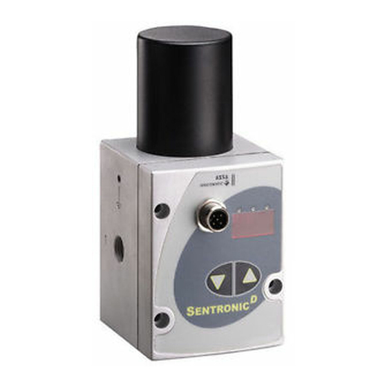
- Page 1 Sentronic Digital Electronic Pressure Regulator Installation Manual...
-
Page 2: Table Of Contents
The information in this manual is subject to change without notice. In no event shall Numatics be liable for technical or editorial errors or omissions. Neither is any liability assumed for accidental or consequential damages arising out of or in connection with the supply or use of the information contained herein. -
Page 3: Description
1 = 0 - 20 mA See Accessories section for required manifold sub-base 2 = 4 - 20 mA Feedback input is needed for dual loop units Information subject to change without notice. For ordering information or regarding your local sales office visit www.numatics.com. -
Page 4: Operating Elements
If the coil current exceeds 1000 mA (DN8) or 560 mA (DN4) for more than 20 seconds, the output current is limited to max. 70% every 4 seconds to prevent the valve from overheating. The yellow LED flashes. Information subject to change without notice. For ordering information or regarding your local sales office visit www.numatics.com. -
Page 5: Electrical Connection
*A 6-wire cable with separate common for the command signal is used for cable lengths over 2 m to minimize the voltage drop for the command signal. Information subject to change without notice. For ordering information or regarding your local sales office visit www.numatics.com. -
Page 6: Analog Setpoint - Outlet Pressure
4.08 mA Span adjustment The span can be set to max. 100% of the maximum outlet pressure (PMR). It can only be decreased. Information subject to change without notice. For ordering information or regarding your local sales office visit www.numatics.com. -
Page 7: Pneumatic Connection
Shut-off: ON; the valve is exhausted at a command signal below 0.5% Controller structure: PID Proportional gain: 4.0 Integration time: 0.1 sec Derivation time: 8 msec Information subject to change without notice. For ordering information or regarding your local sales office visit www.numatics.com. -
Page 8: Field-Programmable Settings
Shut-off at a voltage level higher than 30 volts (+10%). Low voltage: Shut-off at a voltage level lower than 19.5 volts (-10 %). Information subject to change without notice. For ordering information or regarding your local sales office visit www.numatics.com. -
Page 9: Accessories
RS 232 cable converter; 2m cable with 9-pin Sub-D (screw connector) 833-993708 Manifold ships with required hardware and gaskets for connecting manifolds together. 9. Maintenance and Care No special maintenance or care required. Information subject to change without notice. For ordering information or regarding your local sales office visit www.numatics.com. - Page 10 0.98 (25) Programming 1.91 (48.5) 1.10 (28) 2.25 (57.15) interface 2.61 (66.3) 2.20 (56) Mounting holes: M4 thread 0.79 (20) 1.57 (40) 2.60 (66) Information subject to change without notice. For ordering information or regarding your local sales office visit www.numatics.com.
- Page 11 1.61 (41) 1.38 (35) Hole for 2.12 (54) M4 screw 0.31 (8) 0.79 (20) 1.69 (43) 0.55 (14) 1.93 (49) Hole for M4 screw Information subject to change without notice. For ordering information or regarding your local sales office visit www.numatics.com.
- Page 12 2.01 (51) 1.81 (46) Hole for 2.68 (68) 0.31 (8) 1.02 (26) M4 screw 2.01 (51) 0.71 (18) 2.40 (61) Hole for M4 screw Information subject to change without notice. For ordering information or regarding your local sales office visit www.numatics.com.
- Page 13 World Class Supplier of Pneumatic Components World Headquarters USA Numatics, Incorporated Canada Numatics, Ltd Mexico Numatics de Mexico S.A. de C.V. 46280 Dylan Drive P: 519-758-2700 P: 52-222-284-6176 Novi, Michigan 48377 F: 519-452-3995 F: 52-222-284-6179 P: 248-596-3200 F: 248-596-3995 Sentronic Manual Rev 02/12 Numatics, Inc.
Need help?
Do you have a question about the SentronicD and is the answer not in the manual?
Questions and answers