
Related Manuals for Ashcroft LS ATEX Series


Summary of Contents for Ashcroft LS ATEX Series
- Page 1 Installation and Maintenance Instruction Manual Level Switch Model LS for explosion risk areas pursuant to Directive 2014/34/EU (ATEX) In the versions: LS###ATEX IM-LS/ATEX-EN-Rev D 04/2021 1 of 22 095I403-02EN...
-
Page 2: Table Of Contents
Table of Contents: General remarks ................................. 4 Purpose of this manual ............................4 Symbols ................................4 Limitation of liability ............................4 Copyright ................................4 Warranty ................................4 Manufacturer address, customer service ......................4 Safety ..................................5 General sources of danger ..........................5 Intended use .............................. - Page 3 Dismantling & disposal ............................17 11.1 Disassembly ..............................17 11.2 Disposal ................................18 Appendix ................................18 12.1 Data Sheet Level Switch ..........................18 12.2 Declaration of conformity for Level Switch ...................... 19 Page 3 of 22...
-
Page 4: General Remarks
For the product described here we grant warranty according to § 6 warranty for defects, in our General Terms and conditions of delivery and payment. 1.6 Manufacturer address, customer service Ashcroft Instruments GmbH Tel.: +49 (0) 2401/808-888 Fax.: +49 (0) 2401/808-999 Max Planck Street 1 Mail: customer.service@ashcroft.com... -
Page 5: Safety
2 Safety 2.1 General sources of danger Level switches can be part of oleodynamic equipment or fluid reservoirs, in case of damage or leakage of the fluid tank it can result in hazardous situations. The selection of switches should be made in accordance with the applicable standards, regulations and engineering practice. -
Page 6: Personnel Qualification
2.4 Personnel qualification The device may only be installed and commissioned by trained specialist personnel. Specialized personnel are persons who are able to perform the work assigned to them due to their specialized training, experience and knowledge of the country-specific regulations, applicable standards and guidelines. For explosion- protected devices, the personnel must be trained or instructed or authorized to work on explosion-protected devices in hazardous areas. -
Page 7: Intrinsic Safe Execution Ex Ia
3.2 Intrinsic safe execution Ex ia Ambient temperatures for intrinsic safety series: Execution Min. / Max. permissible ambient Temperature class temperature Enclosure with wire - 60°C to +80°C terminals (LS) To avoid additional temperature increase, the devices should not be exposed to direct exposure to sunlight when in operation! When process temperatures for Ex ia are elevated, see below maximum temperature reachable on LS stem/slide bar... -
Page 8: Flameproof Enclosure Execution Ex D
3.2.2 Intrinsic ATEX ia wiring ® For any ASHCROFT Level Switch with intrinsic safety certification (Ex ia) the following electrical parameters have to be considered: = 4 μH and C = 20 pF Power supply parameters: ≤ 30 V and I ≤160 mA... -
Page 9: Special Operating Conditions For Safe Use In Potentially Explosive Atmospheres
3.3.1 Labeling Ex marking Ex marking according to 2014/34/EU according to EN 60079-0 Ex db Ex tb T80°C IIIC CE marking Marking for explosion protection Group II equipment is intended for use in places with explosive gas atmospheres, excluding mine gas and/or dust from hazardous mining operations. -
Page 10: Technical Data
Note 2: In case of power charge piloting, it is necessary to use auxiliary relays or snubbers/suppressors. 4.2 Electrical Wiring ® The wiring of the ASHCROFT Level Switches is available in various configurations: Two, three or four wires sealed cable ... - Page 11 4.2.1 Head type A, AX, B, IAC, IAX, IB 4.2.1.1 Separate wiring Each contact has its own supply Separate wiring / Single contact (SPST) Separate wiring / Double contact(SPDT) Cable colour Cable colour White Black Orange Black Brown White White White Black Blue...
-
Page 12: Marking Of The Device
5 Marking of the device The device is provided with marking on a label or with laser tagging on process connection. The label shows the type designation, serial number, year of manufacture, certificate of approval number, and manufacturer, alternative with limited space type designation, order number and item number. -
Page 13: Structure And Function
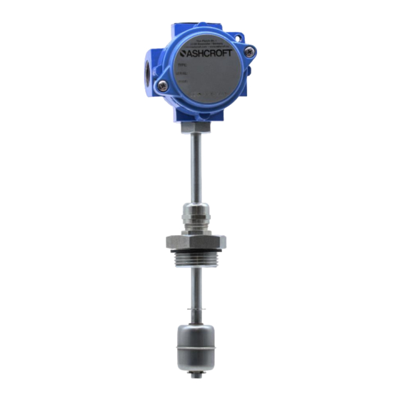
LS=IA Cable Standard (Non ATEX) LS=C or LS=P LS=IBC (cable) LS=IBP (cable gland) LS=IBN (DIN connector) LS=IAC (cable) LS=IAP (cable gland) LS=IAN (DIN connector) 6 Structure and function 6.1 Overview Process connection Stem / Slide bar Float Top level ring stop (Seeger ring) Low level ring stop (Seeger ring) Page 13 of 22... -
Page 14: Functional Description
“ON-OFF“ level switches use reed switches magnetic sensors. This type of contact, hermetically sealed, ® ASHCROFT inert gas filled, are placed inside the slide bar and switched-on when the magnetic float reaches the commutating area. The stroke of each float is limited to the height of the controlled level by suitable ring stops. -
Page 15: Assembly/Installation
8 Assembly/Installation The instruments may be installed from the inside or from the outside of the tank, in according to the selected process connection. The process connection can be threaded or flanged. The level switches are always supplied completed with gasket to be always placed between the tank wall surface and the instrument connection. The correct installation of our level switches must be in vertical position, with 30°... -
Page 16: Electrical Connection
8.4 Electrical connection Take note of the electrical data in the EU design type test certification and the locally applicable regulations and guidelines for installing and operating electrical plant in explosion risk areas (e.g. EN 60079-14, etc.). Connection to be undertaken by authorized and qualified specialist staff only. ... -
Page 17: Cleaning And Maintenance
Incompatible process media Replace level switch with compatible materials ® Bended slide bar/stem Incorrect handling or mounting Send for repair to ASHCROFT Damage to housing or wiring Incorrect handling or mounting Replace/repair level switch at ® ASHCROFT 10.1 Behaviour after rectifying the fault See chapter 8 Assembly/Installation 11 Dismantling &... -
Page 18: Disposal
11.2 Disposal At the end of the product life cycle, do not dispose of this product with normal household waste. Take this product to a collection point or a specialist disposal company for recycling of the components. With the help of the product coding and our data sheet (see Appendix 12.1 available on our website) you will receive the necessary information to be able to carry out a material separation yourself. -
Page 19: Declaration Of Conformity For Level Switch
12.2 Declaration of conformity for Level Switch for Ex ia Page 19 of 22... - Page 20 Page 20 of 22...
- Page 21 12.3 Declaration of conformity for Level Switch for Ex d Page 21 of 22...
- Page 22 Page 22 of 22...
Need help?
Do you have a question about the LS ATEX Series and is the answer not in the manual?
Questions and answers