Table of Contents
Advertisement
Installation and Maintenance
Instruction Manual
Pressure switch model B7, differential pressure switch model D7 and
temperature switch model T7
for explosion risk areas pursuant to Directive 94/9/EC (ATEX) / IEC
In the following configuration:
• B7###CN### pressure switch
• D7###CN### differential pressure switch
• T7###CN### temperature switch
B7
D7
T7
Pressure switch
Differential pressure
Temperature switch
switch
IM-B7D7T7/ATEX-E-Rev A
02/2016
Page 1 of 19
P/N 095I401-02EN
Advertisement
Table of Contents

Related Manuals for Ashcroft D7 series


Summary of Contents for Ashcroft D7 series
-
Page 1: Installation And Maintenance
Installation and Maintenance Instruction Manual Pressure switch model B7, differential pressure switch model D7 and temperature switch model T7 for explosion risk areas pursuant to Directive 94/9/EC (ATEX) / IEC In the following configuration: • B7###CN### pressure switch • D7###CN### differential pressure switch •... -
Page 2: Table Of Contents
Table of contents: General remarks ................................. 4 Purpose of this Manual ............................4 Symbols ................................4 Limits of liability ..............................4 Copyright ................................4 Warranty ................................4 Manufacturer’s address, customer services......................4 Safety ..................................4 General sources of hazards ..........................4 Operator’s responsibility ............................ - Page 3 Removal, disposal ..............................13 11.1 Safety ................................13 11.2 Removal ................................. 13 11.3 Disposal ................................. 14 Appendix ................................14 12.1 Data sheet for switches B7, D7 and T7 ......................14 12.2 EG Declaration of Conformity ........................15 12.3 IECEX Declaration of conformity ........................16 Page 3 of 19...
-
Page 4: General Remarks
For the product described here, we offer a warranty pursuant to Section 6 Guarantee in Respect of Defects in our General Terms and Conditions of Delivery and Payment. 1.6 Manufacturer’s address, customer services Ashcroft Instruments GmbH Tel.: +49 (0) 2401/808-888 Fax.:... -
Page 5: Operator's Responsibility
For each use scenario, the corresponding set-up regulations must be respected. If used in explosion risk areas, the following conditions are to be respected for the individual finishes. 2.2 Operator’s responsibility Safety instructions for proper operation of the device must be respected. They are to be provided by the operator for use by the respective personnel for installation, servicing, inspection and operation. -
Page 6: Use In Explosion Risk Areas Pursuant To Directive 94/9/Ec (Atex)
EU design type test certification: ® The Ashcroft 7XX Series Pressure & Temperature Switches comprise a cylindrical two-part enclosure, consisting of a base and cover, manufactured from die-cast aluminum 380 or stainless steel 316L. The cover treads into the base and is secured against loosening by a 10-32 UNF-2B socket head cap screw. -
Page 7: Technical Data
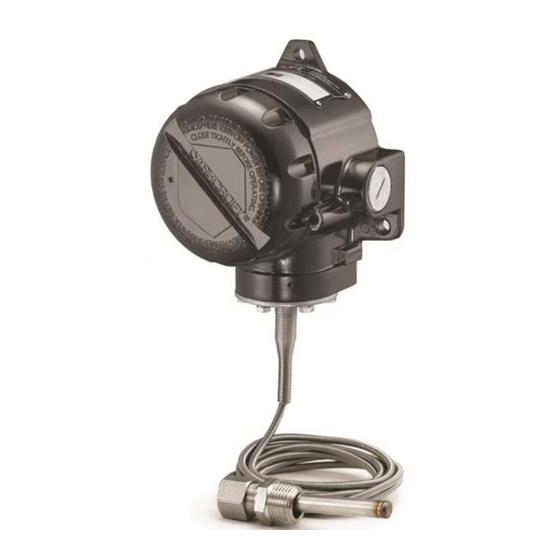
Figure 1 6.2 Description of function The Ashcroft pressure switch is a precision built agency approved control device which features a mechanical snap action switch. Controllers are available for operation on pressure or vacuum, differential pressure or temperature with fixed or variable differential. Also manual reset types for operation on increasing or decreasing pressure. The manual reset types remain tripped until reset by pressing a button on top of the enclosure. -
Page 8: Accessories
6.3.6 Enclosure The Ashcroft snap action pressure switch is furnished in the flameproof NEMA 7 & 9 and ATEX Ex db and dust ignition protected ATEX Ex tb enclosure styles. Enclosure is epoxy coated aluminum casting or optional stainless steel 316L. -
Page 9: Safety
7.1 Safety The switch should be protected against the effects of knocks and impacts. The device should only be transported in the packaging provided. The device should only be transported in a clean condition (free of residues of measuring media). 7.2 Transport inspection The delivery must be checked for completeness and damage during transport. -
Page 10: Mounting/Installation
8.3 Mounting/Installation 8.3.1 Process connection As standard, the device is equipped for pipework mounting with a pressure connection shank pursuant to DIN EN 837- 3. The device is calibrated ex works for vertical installation. Connection to be undertaken by authorized and qualified specialist staff only. ... -
Page 11: Starting Up And Setpoint Adjustment
For accurate setpoint calibration, mount the switch on a calibration stand, a pump or catalog No. 1305 deadweight gauge tester. A suitable reference standard such as an ASHCROFT Duragauge or Test Gauge is necessary to observe convenient changes in pressure. -
Page 12: Subsequent Relocation Of The Switch (By The Customer)
Recommendation: Do not remove the switch from one metering point and fit it in a different place, as there is a risk of the measuring media being mixed, with unforeseeable chemical reactions. 9 Servicing All ASHCROFT switches require little or no maintenance. Be sure that the case is closed at all times. -
Page 13: Safety
When the switch is exposed to process media that may harden and/or build up in the pressure port, the switch should be removed and cleaned as needed. However, to ensure reliable operation and a long lifetime for the device, we recommend that it is checked regularly. 9.1 Safety When undertaking servicing work on the device, the pressure lines must be depressurized, the electrical connections isolated from the mains supply, and the plant secured against being switched on again. -
Page 14: Disposal
When undertaking servicing work on the device, the pressure lines must be depressurized, the electrical connections isolated from the mains supply, and the plant secured against being switched on again. Demount the switch using a suitable tool 11.3 Disposal Please help to protect the environment and dispose of or recycle the devices and components used in accordance with the applicable regulations. -
Page 15: Eg Declaration Of Conformity
12.2 EG Declaration of Conformity Page 15 of 19... -
Page 16: Iecex Declaration Of Conformity
12.3 IECEX Declaration of conformity Page 16 of 19... - Page 17 Page 17 of 19...
- Page 18 Page 18 of 19...
- Page 19 Page 19 of 19...
Need help?
Do you have a question about the D7 series and is the answer not in the manual?
Questions and answers