
Subscribe to Our Youtube Channel
Related Manuals for Garden Oasis Grandview


Summary of Contents for Garden Oasis Grandview
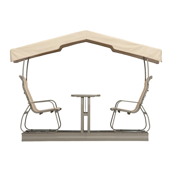
- Page 1 Grandview 4 seat Glider Product Code: D71 M23738 KSN Code: 04733850-4 UPC Code: 749241313264 Date of purchase: _____/ _____/ _____...
- Page 2 SAFETY INFORMATION Please read and understand this entire manual before attempting to assemble, operate or install the product. If any parts is missing or damaged, do not attempt to assemble the product. Two to four people are needed for assembly. In order to avoid damage to the item and its components, use appropriate tools.
-
Page 4: Part List
Part list Item Description Illustration Metal support U shape support Side floor board Center floor board Wheel axle Wheel Upper running 1 Upper running 2 Lower running 1 Lower running 2 Long side guard Short side guard Arm connector Roof cover Side guard... - Page 5 Item Description Illustration Table top Table leg Table bracket Armrest Plastic cap Seat 1 Seat 2 Seat bracket Roof connector Roof tube 1 Roof tube 2 Roof crossbar Roof support bar Roof support bar...
-
Page 6: Hardware Kit
Hardware kit Item Description Illustration Screw 1 M6 x 110mm Screw 2 M6 x 85mm Screw 3 M6 x 65mm Screw 4 M6 x 50mm Screw 5 M6 x 30mm Screw 6 M6 x 20mm Screw 7 M6 x 15mm Screw 8 M6 x 10mm Screw 9 M6 x 70mm Bolt nut... - Page 7 1. Lay out floor board (C) and floor board (D) side by side, stripped face upward as shown. Then connect side floor board (C) with center floor board (D) by using screw 5 (EE), washer (KK), bolt nut (JJ). Repeat this step 7 times.
- Page 8 1. Attached the metal support (A) on the assembled floor board (C, D) by using screw 7 (GG) and washer (KK) as shown. Repeat for the rest metal support (A).
- Page 9 1. Insert wheel axle (E) into wheel (F) and tighten with screw 6 (FF), then open the end of pin (LL) and insert into the hole of wheel (F). Do not over tighten the screws. Repeat on the other end of the wheel axle (E) as shown.
- Page 10 HH HH HH HH 1. Insert lower running 1 (H1) into lower running 2 (H2) and secure by using 4pcs of screw 8 (HH) and washer (KK). Repeat for the rest lower running 1 (H1) and lower running 2 (H2). 2.
- Page 11 1. Turn the floor board over (metal support A facing down), then tighten the metal support (A) onto assembled lower running set (H1, H2) by using screw 4 (DD), washer (KK) and bolt nut (JJ) as figure 1 shown. Do not over tighten the screws. Repeat this step 3 times. 2.
- Page 12 1. Insert upper running 1 (G1) into upper running 2 (G2), then secure with screw 8 (HH) and washer (KK) as figure shown. Repeat for remaining upper running (G1, G2).
- Page 13 1. Insert long side guard (I1) into short side guard (I2), then fasten assembled upper running set (G1, G2) into assembled side guard (I1, I2), align the holes of upper running set (G1, G2) and assembled side guard (I1, I2). Repeat for remaining long side guard (I1), short side guard (I2) and assembled upper running set (G1, G2).
- Page 14 FF FF 1. Connect side guard (L) with both assembled side guard (I1, I2), secure one end section of side guard (L) with one end section of side guard (I2) by using screw 6 (FF), washer (KK) and bolt nut (JJ) as figure shown. Then repeat for another end section of side guard (L) and side guard (I1).
- Page 15 1, Put the assembled (I1, I2, G1, G2, L) onto the assembled (H1, H2, B) as figure shown.
- Page 16 1. Fasten the table leg (N) into the bottom of table top (M) by using screw 6 (FF) and washer (KK) as figure 1 shown. Then secure table bracket (O) and support tube of table top (M) onto the table leg (N) by using screw 6 (FF), washer (KK) and bolt nut (JJ) as figure 2 shown.
- Page 17 1. Connect seat 1 (R1) and seat 2 (R2) as figure shown, insert screw 2 (BB) through washer (KK) and seat 1 (R1), plastic cap ( Q), seat 2 (R2), washer (KK), then secure with bolt nut (JJ) as figure 1 shown. Repeat for remaining seat 1 (R1) and seat 2 (R2).
- Page 18 1. Insert plastic cap (Q) into the plastic sheets hole of seat bracket (S) as figure 1 shown. Then insert screw 2 (BB) through washer (KK) and seat 1 (R1), then into plastic cap (Q) and seat 2 (R2) secure with washer (KK) and bolt nut (JJ) as figure 2 shown. Secure both end section of seat bracket (S) with seat 1 (R1) and seat 2 (R2) by using screw 5 (EE) and washer (KK).
- Page 19 1. Insert screw 9 (II) through washer (KK) and armrest (P) secure with arm connector (J). Repeat for remaining armrest (P) and arm connector (J).
- Page 20 1. Place the assembled seat (R1, R2) onto the assembled armrest (P) as figure shown, then insert screw 1 (AA) into washer (KK) and armrest (P) and plastic cap (Q) secure with seat 1 (R1) and bolt nut (JJ) as figure 1 shown, then repeat this step for other side of seat 2 (R2). Repeat for remaining assembled seat (R1, R2) and assembled armrest (P).
- Page 21 1. Insert screw 6 (FF) into washer (KK) and table leg (N) of assembled table (M, N), then secure with assembled upper running (G1, G2, I1, I2) as figure shown. Repeat for the other side of the table set and upper running set.
- Page 22 1. Place assembled seat set (R1, R2, P) onto the assembled upper running set (G1, G2,), then insert screw 3 (CC) through washer (KK) and armrest (P) secure with bolt nut (JJ) as figure 1 shown. Repeat for remaining assembled seat set (R1, R2, P).
- Page 23 1. Insert screw 5 (EE) through bolt nut (KK) and roof crossbar (W) secure with roof tube 1 (U) as figure 1 shown, then repeat for end section of roof tube 1 (U) with another roof crossbar (W). Repeat for remaining roof crossbar (W) and roof tube 1 (U). 2.
- Page 24 EE EE 1. Insert screw 4 (DD) through washer (KK) and assembled seat (R2) secure with roof support bar (X2) and bolt nut (JJ) as figure 1 shown. Repeat for the remaining roof support bar (X2) and (X1). 2. Insert screw 5 (EE) through washer (KK) and assembled roof crossbar (W) secure with roof support bar (X2) and bolt nut (JJ) as figure 2 shown.
- Page 25 Hook 1. Insert roof tube 2 (V) into roof cover (K) as figure shown, repeat for another roof tube 2 (V). Then place the assembled roof cover onto the top of this item, insert screw 5 (EE) through washer (KK) and roof crossbar (W) secure with roof tube 2 (V), repeat for another side. 2.
- Page 26 steel Canopy Bond Vast Industrial Limited Bao Tang Industrial Jing Lian Chiao Tou Town Dong Guang City Guang Dong Province China 523 538 Please refer to part numbers when reordering For questions or comments about product: Email: customerservice@bondvast.com or Call toll-free: 1-800-961-9838 Made in / Hecho en CHINA Distributed by Sears, Roebuck and Co., Hoffman Estates, IL 60179 sears.com...
Need help?
Do you have a question about the Grandview and is the answer not in the manual?
Questions and answers