Table of Contents
Advertisement
Quick Links
Advertisement
Table of Contents

Subscribe to Our Youtube Channel
Related Manuals for Alcohol Countermeasure Systems Alcolock LR


Summary of Contents for Alcohol Countermeasure Systems Alcolock LR
- Page 1 Installation and Services Manual...
- Page 2 Countermeasure Systems is the trading style of Alcohol Countermeasure Systems Corp. © 2012-2013 Alcohol Countermeasure Systems The information disclosed in this document is the valuable property of Alcohol Countermeasure Systems and all copyright and other proprietary rights to this document are reserved. No reproduction of this document is...
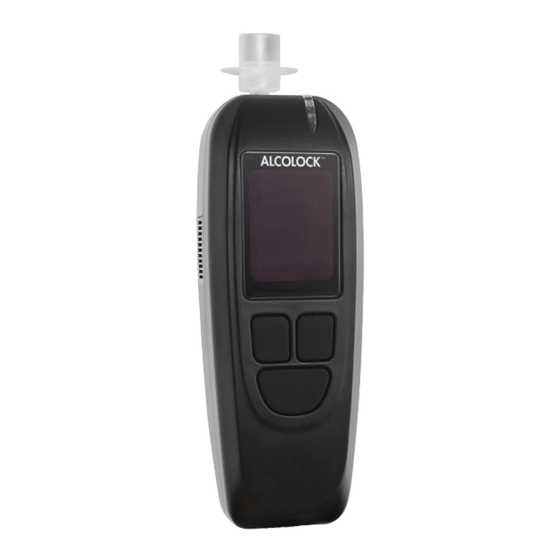
- Page 3 ALCOLOCK LR HANDSET COMPONENTS ALCOLOCK™ LR HANDSET COMPONENTS Indicator Light Air Vent Mouthpiece Sampling Port Display Navigation Buttons* *The Navigation SIDE VIEW Buttons permit the selection of options shown on the display. Cable Input HDMI Port Press the Left, Right, or Bottom...
-
Page 4: Table Of Contents
TABLE OF CONTENTS ALCOLOCK LR alcohol interlock product profile .........1 The ALCOLOCK LR device installation manual ..........1 How to read this manual ..................2 Other required manuals ...................2 Parts and equipment supplied by ACS (the Service Provider) ....3 Tools and equipment supplied by the Service Centre (service facility) ..5 Power tools ....................5... - Page 5 Input odometer reading ................54 22.5 Performing an ITE removal transaction............55 22.6 Removing ECU and restoring the vehicle ............55 23.0 Recycling the ALCOLOCK LR device .............57 24.0 Tampering ......................57 24.1 Signs of tampering ..................57 24.2 Examples of tampering – before and after ..........57 24.3...
-
Page 6: Alcolock Lr Alcohol Interlock Product Profile
THE ALCOLOCK LR DEVICE INSTALLATION MANUAL This manual contains procedures for the installation, monitoring and removal of the ALCOLOCK LR device, as well as wiring diagrams and a glossary of terms. ATTENTION! •... -
Page 7: How To Read This Manual
HOW TO READ THIS MANUAL • For installation of the ALCOLOCK LR device, read sections 5.0 to 20.0 of this manual in the order provided • For wiring diagrams (with and without the external relay), refer to Appendices 3 and 4 of this manual •... -
Page 8: Parts And Equipment Supplied By Acs (The Service Provider)
This section lists parts supplied by ACS, which are required by the Service Centre for the alcohol interlock program; including installation, monitoring, calibration and removal of the ALCOLOCK LR device. Contact ACS to order the following parts (for contact information, refer to acs- corp.com). - Page 9 58-000529 Front clip with brass Enclosure insert 65-000070 Rear clip Enclosure 58-000527 Screw Fastening rear and front clip 45-000129 Plastic plug Covering screw (front clip) 58-000528 Tamper-proof label Covering plastic plug (front clip) Accessories and consumable items for alcohol interlock program: PART # PART DESCRIPTION...
-
Page 10: Tools And Equipment Supplied By The Service Centre (Service Facility)
TOOLS AND EQUIPMENT SUPPLIED BY THE SERVICE CENTRE (SERVICE FACILITY) This section lists parts supplied by the Service Centre, which are required for the installation, monitoring and removal of the ALCOLOCK LR device. POWER TOOLS • Portable reversible battery operated drill with bits •... -
Page 11: Installation Overview
INSTALLATION OVERVIEW To install the ALCOLOCK LR device, complete the following steps in the order provided in this manual. • Inspecting the vehicle electrical system • Mounting the ECU, alarm horn, and (if required) alarm flasher • (Skip if using OBD-II) Locating the tach signal (using DTS, if applicable) •... -
Page 12: Inspecting The Vehicle Charging System
ATTENTION! The alarm horn is intended for installation on vehicles with +12 volt electrical systems only. Locate an alarm horn mounting position under the hood. Ensure that there is sufficient clearance so that closing the hood does not damage the hood or the alarm horn. ALCOLOCK LR... -
Page 13: Mounting The Alarm Flasher (If Required)
Position the alarm horn facing downwards. This is to protect the alarm horn opening from contaminants, such as water leakage and dust. Mount the alarm horn bracket to the vehicle. NOTE: Always use existing hardware and holes to minimize vehicle modification. -
Page 14: Locating The Tachometer Signal Wire
Do not solder or apply heat shrinks or tamper proof labels until all wires have been attached, and post-installation testing has been performed • The ALCOLOCK LR alcohol interlock is a low current device. Use a supplied external relay on vehicles with high-current starter circuits (above 2 amps) •... -
Page 15: Ecu Cable-Wire Summary
• Use supplied heat shrinks or tamper resistant labels on all solder connections. Refer to section 20.0 of this manual • Use supplied tie wraps to neatly incorporate wires into the vehicle wire loom. Keep wires away from vehicle components that move, or that become excessively hot 14.1 ECU CABLE-WIRE SUMMARY... - Page 16 ATTENTION! • The ALCOLOCK LR alcohol interlock is a low current device. Use an external relay on vehicles with high-current starter circuits (above 2 amps) • Refer to Appendix 4 at the back of this manual for the wiring diagram that includes the external relay 13.
-
Page 17: Alarm Horn Wire Connection Steps
NOTE: Step 13 and 14 connections should look as follows: (This illustration shows a sealed connection – do not seal until the installation is verified. Refer to section 20.0 of this manual.) 15. Use supplied tie wraps to neatly incorporate ECU wires with the vehicle wire loom. -
Page 18: Alarm Flasher Wire-Connection Steps (If Required)
Connect ECU wire 11 (Violet) to the ECU wire 1 (red wire of the alarm flasher). Use supplied tie wraps to neatly incorporate the retest alarm wires with the vehicle wire loom. Keep wires away from vehicle components that move, or that become excessively hot. ALCOLOCK LR... -
Page 19: Tachometer Wire-Connection Steps
14.6 TACHOMETER WIRE-CONNECTION STEPS NOTE: • Skip this section if the vehicle tach reading will be obtained using vehicle OBD-II • Section 13.0 provides instructions for locating the tach signal wire from under the hood Attach the vehicle tach signal wire to ECU wire 2 (Green). Use supplied tie wraps to neatly incorporate the tach connection with the vehicle wire loom. -
Page 20: Attaching The Hs And Ecu
Connect the ECU cable (13-001102) to the ECU main input. The cable clicks into place and the ECU beeps. Connect the non-coiled end of the HS cable (13-001100) to the ECU HDMI port. ATTENTION! Do not install the HS enclosure until instructed. ALCOLOCK LR... -
Page 21: Hs Install Procedure And Ite Install Transaction
HS INSTALL PROCEDURE AND ITE INSTALL TRANSACTION After the ALCOLOCK LR device has been connected to the vehicle, perform the HS install procedure by following the steps that appear on the HS screen. The purpose of the HS install procedure is to activate the device and test device functions. -
Page 22: Performing The Hs Install Procedure
Press any navigation button to power up the device. Wait is briefly displayed as the HS powers up. Wait Handset Not Activated is automatically displayed. Handset Not Press and hold the left button to enter Menu. Activated Hold for Menu ALCOLOCK LR... - Page 23 In Menu, press Prev or Next to scroll to Service, then press Select. Menu Service Prev Next Select Input the daily 4-digit service code (press + or – to change a digit, and press Select to move to the next SERVICE CODE digit).
- Page 24 OK is not displayed, press and hold the bottom button to exit the procedure. • Restart the procedure and if the problem persists, check the ECU cable alarm horn and alarm flasher connections, and replace the ECU alarm horn or alarm flasher. ALCOLOCK LR...
- Page 25 Retest Alarm is displayed (even if not used). The HS LED light is off. (If used) the retest alarm flashes. After INSTALL the retest alarm flashes 3 times, OK is displayed. (If a RETEST retest alarm is not used, wait for OK to display). Alarm 11.
-
Page 26: Obd-Ii Select
16.2 OBD-II SELECT OBD SELECT is automatically displayed. NOTE: OBD SELECT • For conventional / non-hybrid vehicles, the ALCOLOCK LR OBD/TACH device must obtain a tach (rpm) reading from under the hood. • Select For non-hybrid vehicles with OBD-II, a tach signal may be Exit obtained by connecting the ECU to vehicle OBD-II. -
Page 27: Obd / Tach
NO OBD OBD SELECT For vehicles not connected to OBD-II, and instead connected to a direct tach source under the hood. NO OBD Select Exit After the correct option has been selected, based on the vehicle and installation type, press OK. Read only one of the following sections of this manual, based on the step 2 selection: •... - Page 28 Press the accelerator pedal and steadily increase the engine rpm to a point slightly above the Run Point rpm threshold value on the third line. (This is to validate the Run Point rpm threshold value that was reset in step 3.) ALCOLOCK LR...
-
Page 29: Obd Speed
If the Run Point value is correct, Turn Off Engine is automatically displayed after the engine rpm exceeds the INSTALL value on the third line. Turn Off Engine Turn the key to the off position. (Press Cancel to return to the Install menu.) Cancel Skip sections 16.2.2 and 16.2.3 and continue to section 16.3 to input the odometer reading. -
Page 30: No Obd
Idling – the vehicle engine rpm reading INSTALL • TACH Idle Point – reset to 0.5 x the Idling engine rpm • Idling 00960 Run Point – reset to 1.5 x the Idling engine rpm Idle Point: 00480 Run Point: 01440 Set Tach Exit ALCOLOCK LR... -
Page 31: Input Odometer Reading
Next is displayed at the bottom-left of the screen. INSTALL TACH If the tach thresholds are correct, press Next (otherwise Idling 00960 press Set Tach until a correct tach threshold is obtained). Idle Point: 00480 Run Point: 01440 Set Tach Next Exit After Next is pressed, ACCELERATE is displayed, along... -
Page 32: Performing An Ite Install Transaction
ITE application manual • UCS instruction manual • Download Station Manual When the ITE transaction is complete, connect the HS back to the ECU. The client’s name is displayed. INSTALL Client Press the left navigation button to activate. Name Activate ALCOLOCK LR... -
Page 33: Post-Installation Testing
With the vehicle in park or neutral, turn on the vehicle engine for a short period. NOTE: Refer to the instruction manual for more information about using the ALCOLOCK LR device. 18.0 ATTACHING THE SECURITY ENCLOSURE Attach the security enclosure only after doing the following: •... - Page 34 Insert the plastic plug (58-000528) into the screw hole of the rear clip, covering the screw. Apply a tamper-proof label (65-000070) to the rear clip, over the glossy rectangular area that surrounds the plastic plug. ALCOLOCK LR...
-
Page 35: Attaching The Gps Antenna (If Required)
19.0 ATTACHING THE GPS ANTENNA (IF REQUIRED) The GPS module (04-000001) is attached separately to the ECU. The GPS module consists of a cable plug and an antenna with an adhesive strip. Attach the GPS cable plug onto the communication port at the bottom of the ECU. - Page 36 Reinstall all vehicle panels. Perform a final visual inspection. Ensure that the vehicle is returned to its original appearance. *YOU HAVE COMPLETED THE INSTALLATION OF THE ALCOLOCK LR ALCOHOL INTERLOCK DEVICE* ALCOLOCK LR...
-
Page 37: Hs Monitor Procedure, Ite Calibration And Monitor Transactions
21.0 HS MONITOR PROCEDURE, ITE CALIBRATION AND MONITOR TRANSACTIONS During routine monitoring appointments, perform the HS monitor procedure by following the steps that appear on the HS screen. The purpose of the HS monitor procedure is to test device functions. At the end of the HS monitor procedure, detach the HS from the vehicle and connect it to a PC via a Download Station (79-008952) or Universal Calibration Station (79-007302), to perform the ITE calibration and monitor transactions. -
Page 38: Performing The Hs Monitor Procedure
0000 After setting the last digit, press Select. Select With the correct code entered, press Accept; otherwise, press Correct to re-enter the service code, or press SERVICE CODE Cancel to return to Main Menu. 3729 Cancel ACCEPT Select ALCOLOCK LR... - Page 39 In the SERVICE menu, press Prev or Next to scroll to Monitor, then press Select. SERVICE Monitor Prev Next Select Wait is briefly displayed as the monitor procedure loads. Wait NOTE: MONITOR will display at the top of the screen during the HS monitor procedure.
- Page 40 12. Turn the ignition key to the on position. Relay: The vehicle engine cannot be started because the Relay Exit is OFF. Turn Ignition OFF is displayed. MONITOR Ignition: ON and Relay: OFF are displayed. Turn Ignition Ignition: ON Relay: Exit ALCOLOCK LR...
- Page 41 13. Turn the key to the off position. Turn Ignition ON is displayed. Ignition: OFF and Relay: ON are displayed. MONITOR Turn Ignition Ignition: OFF Relay: Exit ATTENTION! • Before starting the ignition, ensure that the vehicle is in the park / neutral position, with parking brake engaged, to prevent the vehicle from moving •...
-
Page 42: Obd-Ii Select
21.2 OBD-II SELECT OBD SELECT is automatically displayed. OBD SELECT NOTE: • For conventional / non-hybrid vehicles, the ALCOLOCK LR OBD/TACH device must obtain a tach (rpm) reading from under the hood. • Select For non-hybrid vehicles with OBD-II, a tach signal may be... -
Page 43: Obd / Tach
21.2.1 OBD / TACH NOTE: Read this section for non-hybrid vehicles where the tach was obtained through OBD-II. After selecting the OBD / TACH option in the previous screen, TACH is displayed, along with the following: MONITOR • Idling – the vehicle engine rpm reading TACH NOTE: Idling... - Page 44 Turn Off Engine Turn the key to the off position. (Press Cancel to return to the Monitor menu.) Cancel Skip sections 21.2.2 and 21.2.3 and continue to section 21.3 to input the odometer reading. ALCOLOCK LR...
-
Page 45: Obd Speed
21.2.2 OBD SPEED NOTE: Read this section for hybrid vehicles only. After selecting the OBD/SPEED option in section 21.2 “OBD Select”, CHECK SPEED is displayed. MONITOR CHECK SPEED Speed is displayed at 0, however the value may slightly fluctuate. Speed 00000 The OBD-II speed threshold is already programmed into Exit... - Page 46 Idle Point: 00480 • Run Point: 01440 Run Point – the reset rpm threshold value Exit ATTENTION! Ensure that the vehicle is in the park / neutral position, with parking brake engaged, to prevent the vehicle from moving. ALCOLOCK LR...
-
Page 47: Input Odometer Reading
Press the accelerator pedal and steadily increase the engine rpm to a point slightly above the Run Point rpm threshold value on the third line. (This is to validate the Run Point rpm threshold value that was reset in step 3.) If the Run Point value is correct, Turn Off Engine is automatically displayed after the engine rpm exceeds the MONITOR... -
Page 48: Performing The Ite Calibration And Monitor Transactions
Press and hold the left navigation button to activate. Name Activate Ready for Test is displayed along with the client’s last name. The HS monitor procedure and ITE monitor transaction are complete. Continue to the next section. Ready for Test Name Hold for Menu ALCOLOCK LR... -
Page 49: Device Removal Overview
22.0 DEVICE REMOVAL OVERVIEW A device removal is performed at the end of program. The following procedures must be completed in the order provided: • Running an HS removal procedure, following the steps that appear on the HS display • Running an ITE removal transaction •... -
Page 50: Performing The Hs Removal Procedure
Service Prev Next Select Input the daily 4-digit service code (press + or – to change a digit, and press Select to move to the next SERVICE CODE digit). 0000 After setting the last digit, press Select. Select ALCOLOCK LR... - Page 51 With the correct code entered, press Accept; otherwise, press Correct to re-enter the service code, or press SERVICE CODE Cancel to return to Main Menu. 3729 Cancel ACCEPT Corect In the SERVICE menu, press Prev or Next to scroll to Removal, then press Select.
- Page 52 Turn Ignition ON is displayed. REMOVAL Ignition: OFF and Relay: OFF are displayed. Turn Ignition 12. Turn the ignition key to the on position. Ignition: OFF Relay: The vehicle engine cannot be started because the Relay Exit is OFF. ALCOLOCK LR...
- Page 53 Turn Ignition OFF is displayed. REMOVAL Ignition: ON and Relay: OFF are displayed. Turn Ignition Ignition: ON Relay: Exit 13. Turn the key to the off position. Turn Ignition ON is displayed. Ignition: OFF and Relay: ON are displayed. REMOVAL Turn Ignition Ignition: OFF Relay:...
-
Page 54: Obd-Ii Select
22.3 OBD-II SELECT OBD SELECT is automatically displayed. OBD SELECT NOTE: • For conventional / non-hybrid vehicles, the ALCOLOCK LR OBD/TACH device must obtain a tach (rpm) reading from under the hood. • Select For non-hybrid vehicles with OBD-II, a tach signal may be Exit obtained by connecting the ECU to vehicle OBD-II. -
Page 55: Obd / Tach
22.3.1 OBD / TACH NOTE: Read this section for non-hybrid vehicles where the tach was obtained through OBD-II. After selecting the OBD / TACH option in the previous screen, TACH is displayed, along with the following: REMOVAL • Idling – the vehicle engine rpm reading TACH Idling 00960... - Page 56 Turn Off Engine Turn the key to the off position. (Press Cancel to return Cancel to the Removal menu.) Skip sections 22.3.2 and 22.3.3 and continue to section 22.4 to input the odometer reading. ALCOLOCK LR...
-
Page 57: Obd Speed
22.3.2 OBD SPEED NOTE: Read this section for hybrid vehicles only. After selecting the OBD/SPEED option in section 22.3 “OBD Select”, CHECK SPEED is displayed. REMOVAL Speed is displayed at 0, however the value may fluctuate CHECK SPEED slightly. Speed 00000 The OBD-II speed threshold is already programmed into Exit... - Page 58 Press the accelerator pedal and steadily increase the engine rpm to a point slightly above the Run Point rpm threshold value on the third line. (This is to validate the Run Point rpm threshold value that was reset in step 3.) ALCOLOCK LR...
-
Page 59: Input Odometer Reading
If the Run Point value is correct, Turn Off Engine is automatically displayed after the engine rpm exceeds the REMOVAL value on the third line. Turn Off Engine Turn the key to the off position. (Press Cancel to return to the Removal menu.) Cancel Continue to the next section. -
Page 60: Performing An Ite Removal Transaction
A. Disconnect ECU wire 2 (Green) from the wire from the tachometer location under the hood. B. Use a heat shrink to restore the tachometer wire to its original condition. Disconnect ECU wire 12 (Orange) from the red (positive) wire of the alarm horn and alarm flasher. ALCOLOCK LR... - Page 61 If a retest alarm was used (for the hearing-impaired) disconnect ECU wire 6 (Pink) from the red (positive) wire of the retest alarm and disconnect ECU wire 11 (Violet) from ECU wire 1 (Red). Disconnect ECU wires 10 (Blue-Yellow) and 9 (Light Blue) from the wire that was cut during installation (Wire 10 and Wire 9 are connected in series with this wire).
-
Page 62: Recycling The Alcolock Lr Device
23.0 RECYCLING THE ALCOLOCK LR DEVICE Following the removal, devices (ECU, HS, or both) that are functioning correctly will remain at the Service Centre. Devices in need of repair, or at the end of their service life, must be returned to ACS. - Page 63 Tamper resistent label over vehicle grounding: Tamper seal over security enclosure (front clip): HS screw plugs (x4): INSTALLATION MANUAL...
-
Page 64: Signs Of Tampering -- Event Log
ATTENTION! • Any signs of tampering must be detailed in the Tamper Report (refer to Appendix 1 in this manual) • Tampering is not limited to these areas. Inspect the entire ALCOLOCK LR device EVENT DESCRIPTION WHERE TO INSPECT (WITH RECALL NUMBER) -
Page 65: Tamper Report Procedure
The service technician must resolve any matters surrounding the functioning of the ALCOLOCK LR device. NOTE: If the event was not caused by a mechanic, it must be documented in the occurrence report. -
Page 66: Appendices
Tamper Type: Date of Tamper: Time of Tamper: Comments: Violation Type Indicate all Violations Power Off/ Power On Recall Picture Start Violation Picture Other Picture Other Alcohol Countermeasure Systems FAX (1) COPY OF THIS ALCOLOCK @________________ FORM TO: ALCOLOCK LR... -
Page 67: Appendix 2: Glossary
(HS or ECU): Performed on ITE when an installed HS or ECU requires replacement. handset (HS): Part of the ALCOLOCK LR device that is used to conduct breath alcohol tests and communicate with the driver. INSTALLATION MANUAL... - Page 68 HDMI (high-definition multimedia interface): The ALCOLOCK LR device HS and ECU are each equipped with an HDMI receptacle. GPS: Global positioning system. idle threshold: The tach signal (rpm) value at which the vehicle engine is turned on without pressing the accelerator pedal. During the HS install, monitor and removal procedures, the alcohol interlock device sets the idle threshold at 0.5 x idling...
- Page 69 The tach signal (rpm) value at which the vehicle engine is on with the accelerator pedal pressed. During the HS install, monitor and removal procedures, the ALCOLOCK LR device sets the vehicle run threshold at 1.5 x idling engine rpm.
-
Page 70: Appendix 3: Lr Circuit Diagram (Low-Current Vehicles)
APPENDIX 3: LR CIRCUIT DIAGRAM (LOW-CURRENT VEHICLES) ALCOLOCK LR... -
Page 71: Appendix 4: Lr Circuit Diagram (With External Relay)
APPENDIX 4: LR CIRCUIT DIAGRAM (WITH EXTERNAL RELAY) INSTALLATION MANUAL... - Page 72 INM-ENG-60-000249-B © 2012-2013...
Need help?
Do you have a question about the Alcolock LR and is the answer not in the manual?
Questions and answers