
Related Manuals for VP instruments VPFlowScope

Summary of Contents for VP instruments VPFlowScope
- Page 1 VPINSTRUMENTS.COM VPFlowScope probe User manual © 2019 VPInstruments MAN-VP-SPRO-EN-1901 Date: 04-07-2019...
- Page 2 VPFlowScope probe © 2019 VPInstruments Al l ri ghts res erved. No pa rts of thi s document ma y be reproduced i n a ny form or by a ny mea ns - gra phi c, el ectroni c, or mecha ni ca l , i ncl udi ng photocopyi ng, recordi ng, ta pi ng, or i nforma ti on s tora ge a nd retri eva l s ys tems - wi thout the wri tten permi s s i on of the publ i s her.
-
Page 3: Table Of Contents
Table of Contents 1 Warning - Read this first 2 Introduction 3 Product overview 1 Configuration ........................... 7 2 VPFlowScope probe with connector cap ........................... 8 3 VPFlowScope probe with display ........................... 8 4 VPFlowScope probe with the VPFlowTerminal ........................... 8... - Page 4 12 Order information and accessories 13 Appendix A - UL © 2019 VPInstruments | MAN-VP-SPRO-EN | Revision: 1901 | Date: 04-07-2019...
-
Page 5: Warning - Read This First
When polluted, gently clean the sensor using demineralized water or cleaning alcohol. Precision instruments need regular re-calibration. To keep your VPFlowScope probe in best shape, it needs recalibration. We advice annual recalibration. Not intended for fiscal metering or billing. Our flow meters are not certified for fiscal metering. -
Page 6: Introduction
Introduction Congratulations! You purchased the easiest to use and most complete compressed air measurement tool in the world. With the VPFlowScope probe, you can monitor and record flow, pressure, temperature, and total air consumption, simultaneously. Great products deserve great user manuals. We have done our best to make this user manual as complete as possible. -
Page 7: Product Overview
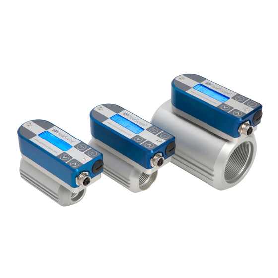
For all models, all parameters and outputs are available. The VPFlowScope probe is available in 2 lengths. Additional options are available for both types: Order Code... -
Page 8: Vpflowscope Probe With Connector Cap
VPFlowScope probe with connector cap The VPFlowScope probe with connector cap can be used in applications where local read-out and data logging is not required. With it's various outputs the VPFlowScope probe can be connected to remote data loggers. VPFlowScope probe with display The display module adds a 3 row display with keypad and an optional 2 Million point data logger(optional) to the VPFlowScope probe. -
Page 9: Quick Start
Find the best point of installation for this product. Make sure that all specifications are met. · For installation of the VPFlowScope probe, an insertion point needs to be created. You can weld a tap with minimum internal 1/2 inch thread or use a hot tap saddle. -
Page 10: Measurement
See chapter 9.1 for details. Pressure The VPFlowScope probe features a built-in gauge pressure sensor. The sensor range is 0 .. 16 bar | 0 .. 250 psi gauge. The sensor cannot measure vacuum, please contact us if you have a vacuum application. -
Page 11: Totalizer
Totalizer The totalizer keeps track of the total consumed amount of compressed air in normal cubic meters, or in scf depending on which unit you choose to read out. The refresh interval is 1 second, actual measurement data will be available on the display and by Modbus. For back up reasons, the totalizer value is written to it's internal memory with an interval of 15 minutes. -
Page 12: Mechanical Installation
Use a ball valve to insert and retract the VPFlowScope probe when you want. Use a 1/2 inch full bore ball valve or a 3/4 inch ball valve. The VPInstruments hot tap drill has a 1” drill size. In that case, place a 1”... - Page 13 (see picture). Never install the instruments upside down. When mated to a display, the VPFlowScope DP is shaped to make alignment with the flow direction easy. The display should point downstream of the flow. With a connector cap, the M12 connector points downstream of the flow.
- Page 14 SAFETY FIRST: START WITH MOUNTING THE SAFETY LINE! The VPFlowScope probe is mounted with a 1/2 inch compression fitting. The probe is sealed with a Teflon ferrule instead of a stainless steel ferrule. Teflon may become slippery. The safety line will keep the sensor secure when it accidentally moves out of the compression fitting.
- Page 15 Step 1. Step 2. 1. Keep the ball valve closed! 1. Insert the VPFlowScope probe until it hits the 2. Insert the compression fitting in ball valve. Use ball valve. The probe remains in the compression Teflon tape or liquid sealant.
- Page 16 Step 3. Step 4. 1. Keep the ball valve closed! 1. Insert the VPFlowScope probe until it hits the 2. Insert the compression fitting in the ball valve. ball valve. The probe remains in the compression Use Teflon tape or liquid sealant.
- Page 17 Step 5. Step 6. 1. Keep your hand on top of the VPFlowScope 1. Unscrew the safety lock and pull the safety probe line tight 2. Tighten the safety lock When you install the VPFlowScope probe 3. Align the flow direction. Alignment by the eye...
-
Page 18: Piping Table
The following table provides a guideline for proper distances between upstream or downstream objects and the VPFlowScope probe. The upstream length is the length between the last non-straight object and the VPFlowScope probe. If the upstream length is straight, and the distortion is downstream of the VPFlowScope probe, you can use the column "downstream length"... -
Page 19: Flow Range Table
Flow range table Schedule 40 standard seamless carbon steel pipe Flow Size (inch) Inch Min (scfm) Max (scfm) Min (m /hr) Max (m /hr) 52.5 1,169 77.9 1,516 2,576 102.3 2,610 4,435 154.1 5,924 10,065 202.7 10,259 17,429 10.2 259.1 16,756 28,468 11.9... -
Page 20: Display
The VPFlowScope display can be powered up without a sensor being connected. In this case a "no sensor" message will be shown when the device. Always connect a sensor to ensure proper operation. Display status icons Some status icons show feedback on the meters' status. -
Page 21: Data Logger
Data Logger The optional integrated data logger offers you 2 Million data points. Enough to measure all three channels 1 x per second for more than a week. Use the following guidelines for the intervals Application Flow Pressure Temperatur Estimated log time* Standard energy management 5 min... -
Page 22: Menu
Menu The menu is categorized into 3 main items which contain their own sub menu items. The complete menu structure is shown below: 1. Settings 1. Diameter 2. Display 3. Date and Time 4. Modbus address 5. RS485 6. Display dim time 7. - Page 23 The Modbus address can be changed with this option. Use the up and down buttons to change the number. Available numbers 1 – 247. After setting the number press enter to save the address. The power of the VPFlowScope probe needs to be cycled to activate the new address.
-
Page 24: Vpstudio Software
Connect the VPFlowScope probe to the computer The VPFlowScope probe can be connected to the computer with the M12 connector from the JB5 interface box. This interface box combines the power and data signals. Power up the device by connecting the 24VDC power supply to the JB5 interface box. -
Page 25: Electrical Connections
CONNECT THE M12 CONNECTOR BEFORE POWERING UP THE INSTRUMENTS. The VPFlowScope probe provides a 4 .. 20 mA / pulse output and a Modbus output. All signals are present in the M12 connector. These outputs can be used to connect the VPFlowScope probe to a building management system or energy monitoring system like VPVision. - Page 26 For scaling purposes, the zero and span matching 4 and 20mA can be modified. This will not effect the original measurement range. The zero and span are only used to increase or narrow the resolution. For bi-directional measurement, the zero value needs to be set negative. See below table for factory defaults.
-
Page 27: Pulse Output
Pulse output The VPFlowScope probe features a low-frequency active pulse output. The pulse is a ‘non potential’ free output as it acts like a controlled current output. To make it passive, an external isolator can be used. The pulse interval can be set with the VPStudio software. A pulse from 0 .. 20 mA will be generated when the interval exceeds. -
Page 28: Modbus Interface
Modbus interface Introduction to Modbus For a complete introduction on the Modbus standard can be found on www.modbus.org. See the document Modbus_over_serial_line_V1_02.pdf, which can be downloaded from their website. We strongly recommend to download and read this information carefully before installing Modbus communication. - Page 29 Register map The actual measurement data is placed in holding registers. To read out data, you will need to use the corresponding holding register. All data is stored in 2 16-bit registers with below register number as start address. Read out the data with this start address and length 2. Decimal Description Type...
- Page 30 * Writing to the totalizer will reset the totalizer to zero. Available write operations Option Data Description 4 .. 20 mA unit /sec /min SCFM /min sfps °C Other °F /sec 4 .. 20 mA min Decimal value 4 .. 20 mA max Decimal value Diameter 25 - 1016 mm...
- Page 31 1 KΩ Bus power The VPFlowScope probe can be powered via the same trunk line. 2 separate wires are used for power + and power -. Take in account that long wires with multiple slaves will cause voltage drops. The minimum supply voltage is 12VDC measured at the last VPFlowScope probe in the daisy chain.
-
Page 32: Service
News on software and firmware updates can be found on www.vpinstruments.com, or are provided by your local re-seller. The VPFlowScope probe sensor can be updated via the RS485 port. A special display update cable is used for updating the firmware of the display. This cable is available on request. -
Page 33: Specifications
Specifications Please always check the label of your product for the specifications. Specifications are subject to change as we are continuously improving our products. Please contact us to obtain the latest specification sheet. Flow sensor (minimum detection level and max flow rate shown) Flow range 0.5 .. - Page 34 JB5 interface kit with 5m / 16.4ft cable + 24 VDC power supply + RS485 to USB converter VPA.0003.005 Compression fitting for VPFlowScope 400mm probe with adjustable integrated safety system VPA.0001.000 Compression fitting 0,5" NPT for insertion probes with Teflon ferrule VPA.0001.001...
- Page 35 Electrical connection guidelines- UL 508 Listing for USA & Canada (Check label to see if product is UL marked) The VPFlowScope is intended to be used with a Class 2 power source or Class 2 transformer in accordance with UL1310 or UL1585. As an alternative a LVLC (Low Voltage Limited Current) power source, with the following properties can be used: ·...
- Page 36 easy insight into energy flows VPInstruments Buitenwatersloot 335 2614 GS Delft The Netherlands info@vpinstruments.com www.vpinstruments.com MAN-VP-SPRO-EN-1901 Date: 04-07-2019...
Need help?
Do you have a question about the VPFlowScope and is the answer not in the manual?
Questions and answers