
Related Manuals for GiBiDi BARR500


Summary of Contents for GiBiDi BARR500
- Page 1 BARR500 BARR500 - (524 - 526) Barriere elettromeccaniche ISTRUZIONI PER L’INSTALLAZIONE Electromechanical barriers INSTRUCTIONS FOR INSTALLATION...
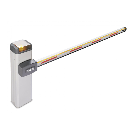
- Page 2 La nuova barriera automatica di tipo elettromeccanico a 24Vdc per gestire facilmente impianti fino ad 6 m d'asta ad alta velocità d'apertura. Con un design contemporaneo e nuove soluzioni tecnologiche, BARR500 è la risposta giusta a tutte queste esigenze. Predisposte per un facile adeguamento alla Normativa EN 12453.
- Page 3 BARR500 ATTENZIONE: IMPORTANTI ISTRUZIONI DI SICUREZZA. E' importante per la sicurezza delle persone seguire queste istruzioni. Una errata installazione o un errato uso del prodotto può portare a gravi danni alle persone Conservare il presente libretto di istruzioni, leggere attentamente prima di iniziare l’installazione AVVERTENZE PER L’UTENTE...
- Page 4 BARR500 DATI TECNICI OPERATORE BARR524 BARR526 Motore elettrico 24Vdc 1600 RPM 24Vdc 3350 RPM 220/230Vac 50-60Hz Tensione di alimentazione Alimentazione motore 24Vdc 24Vdc Potenza assorbita MAX 150W MAX 200W Temperatura esercizio -20°C +60°C -20°C +60°C Grado di protezione IP 44...
-
Page 5: Avvertenze Preliminari
BARR500 AVVERTENZE PRELIMINARI • Nel campo di azione dell'operatore non devono essere presenti ostacoli di qualsiasi genere. • La posa del plinto di fondazione deve avvenire in una zona di terreno libera da cavi e tubature e di caratteristiche tali da garantire una adeguata tenuta del plinto. - Page 6 BARR500 CONVERSIONE DESTRO-SINISTRO DELLA SBARRA 1 - Svitare i due grani 1 (13) di fermo ed i due grani lunghi 2 (13) che fungono da finecorsa meccanico. 2 - Sbloccare l'operatore con la chiave 3 (13) in dotazione agendo sull'asta dello sblocco 4 (13).
- Page 7 BARR500 INSTALLAZIONE DELLE MOLLE Le barriere BARR524 e BARR526 vengono fornite senza molle che vanno scelte in base alla lunghezza dell'asta ed in base agli accessori montati sull'asta stessa. Una volta scelte le molle giuste per la specifica installazione seguire queste semplici istruzioni: Sbloccare l'operatore(vedi capitolo MANOVRA MANUALE) Portare manualmente l'asta in posizione verticale.
- Page 8 BARR500 OPTIONAL PER PROFILO ASTA 100x66 mm Lunghezza asta (m) Asta Asta + Luci Asta + Costa Asta + Costa + Luci Asta + Piedino Asta + Piedino + Luci Asta + Piedino + Costa Asta + Piedino + Costa + Luci...
- Page 9 BARR500 REGOLAZIONE FINECORSA MECCANICI I Finecorsa meccanici possono essere regolati agendo su due grani accessibili dai fori 1 e 2 (26) presenti sulla piastra di supporto del contenitore apparecchiatura. Per accedere ai due grani lunghi di regolazione bisogna svitare completamente i due grani corti che hanno la funzione di bloccare i grani lunghi.
- Page 10 BARR500 REGOLAZIONE FINECORSA ELETTRICI La regolazione dei finecorsa elettrici va sempre effettuata ad operatore scollegato dalla rete elettrica. Rimuovendo il cofano frontale è possibile accedere al gruppo dei finecorsa elettrici che è costituito da: • Un disco in acciaio inox fisso da non muovere 1(29).
-
Page 11: Accessori Disponibili
BARR500 DISINSTALLAZIONE DEI GIUNTI SUPPORTO ASTA Se è presente la molla e si pensa che in seguito alla rimozione dei giunti asta sia necessario sbloccare l'operatore provvedere a seguire prima la procedura Sgancio del dispositivo di bilanciamento 1 - L'asta deve essere in posizione orizzontale. -
Page 12: Manutenzione
BARR500 LUCI ASTA (38) Sul profilo standard dell'asta è possibile montare due tubi luminosi per aumentare la visibilità dell'asta. La figura 38 mostra la modalità corretta per l'installazione del tubo luminoso, il cavo di alimentazione (1) passa nella parte cava interna dell'asta, all'interno dell'asta questo si congiunge con il tubo luminoso (3) il quale trova poi alloggiamento nelle sedi appositamente ricavate sul profilo fino a terminare dallo stesso lato del cavo di alimentazione (2). - Page 13 BARR500 Dichiarazione di conformità CE Il fabbricante: GI.BI.DI. S.r.l. Via Abetone Brennero, 177/B, 46025 Poggio Rusco (MN) ITALY Dichiara che i prodotti: BARRIERE ELETTROMECCANICHE BARR524-526 Sono conformi alle seguenti Direttive CEE: • Direttiva EMC 2004/108/CE e successive modifiche; e che sono state applicate le seguenti norme armonizzate: •...
-
Page 14: Manutenzione Straordinaria
BARR500 MANUTENZIONE STRAORDINARIA Data: Timbro ditta installatrice: Firma tecnico: Data Annotazioni Firma Tecnico Data: Timbro ditta installatrice: Firma tecnico: Data Annotazioni Firma Tecnico... -
Page 15: Installation Warnings
The new 24 VDC automatic electromechanical barrier for easy system control with booms of up to 6 metres and high- speed opening. With a contemporary design and new technological solutions, BARR500 is the right answer to all these requirements. Designed for easy adaptation to the EN 12453 standards. -
Page 16: Warnings For The User
BARR500 WARNINGS FOR THE USER In the event of an operating fault or failure, cut the power upstream of the control unit and call Technical Service. Periodically check good functioning of the safety devices. Any repairs must be carried out by specialised personnel using original and certified materials. - Page 17 BARR500 TECHNICAL DATA OPERATOR BARR524 BARR526 Electric motor 24Vdc 1600 RPM 24Vdc 3350 RPM 220/230Vac, single-phase, 50-60Hz Supply voltage Motor power supply 24Vdc 24Vdc Power absorbed MAX 150W MAX 200W Operating temperature -20°C +60°C -20°C +60°C Degree of protection IP 44...
-
Page 18: Preliminary Warnings
BARR500 PRELIMINARY WARNINGS • There must not be obstacles of any kind in the range of action of the operator. • The foundation plinth must be laid in an area free of cables and ducts and such as to guarantee adequate hold of the plinth. - Page 19 BARR500 RIGHT-LEFT BOOM CONVERSION 1 - Unscrew the two locking grub screws 1 (13) and the two long grub screws 2 (13) that act as mechanical end stop. 2 - Release the operator with the wrench 3 (13) provided acting on the release rod 4 (13).
-
Page 20: Spring Installation
BARR500 SPRING INSTALLATION The BARR524 and BARR526 barriers are supplied without springs, which must be chosen based on the length of the boom and the accessories fitted on the boom. Once you have chosen the right springs for the specific installation, follow these simple instructions: 1 - Release the operator (see the section MANUAL MANOEUVRE) 2 - Move the boom into vertical position by hand. - Page 21 BARR500 Boom lenght (m) OPTIONALS AVAILABLE FOR BOOM OUTLINE 100x66 mm Boom Boom Lights Boom Edge Boom Edge Lights Boom End Foot Boom End Foot Lights Boom End Foot Edge Boom End Foot Edge Lights Boom Rack Boom Rack Lights...
-
Page 22: Control Unit Installation
BARR500 MECHANICAL END-STOP ADJUSTMENT The mechanical end-stops can be adjusted by acting on the two grub screws accessible through the holes 1 and 2 (26) in the support plate of the control unit container. To access the two long adjustment grub screws, completely unscrew the two short grub screws that lock the long grub screws. - Page 23 BARR500 ELECTRICAL LIMIT SWITCH ADJUSTMENT The electrical limit switches must always be adjusted with the operator disconnected from the mains. Remove the front cover to access the limit switch unit composed of: • A fixed stainless steel disc 1 (29) that must not be moved.
-
Page 24: Accessories Available
BARR500 BOOM SUPPORT COUPLING UNINSTALLATION If the spring is fitted and you think that the operator will need to be released after removing the boom coupling, first follow the Balancing device detachment procedure. The boom must be in horizontal position. -
Page 25: Maintenance
BARR500 BOOM LIGHTS (38) Two light tubes can be fitted on the standard boom profile to enhance boom visibility. Figure 38 shows the correct way to install the light tube. The power cable (1) runs through the hollow section of the boom where it is connected to the light tube (3) which in its turn is housed in the seats cut into the profile until terminating at the same side as the power cable (2). - Page 26 BARR500 CE Declaration of conformity The manufacturer: GI.BI.DI. S.r.l. Via Abetone Brennero, 177/B, 46025 Poggio Rusco (MN) ITALY Declares that the products: ELECTROMECHANICAL BARRIERS BARR524-526 Are in conformity with the following CEE Directives: • EMC Directive 2004/108/CE and subsequent amendments;...
-
Page 27: Extraordinary Maintenance
BARR500 EXTRAORDINARY MAINTENANCE Date: Date: Installer company stamp: Installer company stamp: Technician sign: Technician sign: Date Date Notes Notes Technician sign Technician sign Date: Date: Installer company stamp: Installer company stamp: Technician sign: Technician sign: Date Date Notes Notes Technician sign... -
Page 28: Instructions Pour L'installation
La nouvelle barrière automatique de type électromécanique à 24Vcc pour gérer facilement des installations ayant jusqu'à 6 m de lisse à grande vitesse d'ouverture. Avec un design contemporain et de nouvelles solutions technologiques, BARR500 est la réponse exacte à toutes ces exigences. Prévues pour une adaptation aisée à la Norme EN 12453. - Page 29 BARR500 MISE EN GARDE POUR L'UTILISATEUR En cas de panne ou de dysfonctionnements, il faut couper le courant en amont de l'appareil et faire appel au service après vente. Contrôler périodiquement le fonctionnement des dispositifs de sécurité. Les éventuelles réparations doivent être exécutées par un personnel spécialisé qui utilise des matériels d'origine et certifiés.
-
Page 30: Caracteristiques Techniques
BARR500 CARACTERISTIQUES TECHNIQUES OPÉRATEUR BARR524 BARR526 Moteur électrique 24Vdc 1600 RPM 24Vdc 3350 RPM Tension d'alimentation 220/230Vac 50-60Hz Alimentation moteur 24Vdc 24Vdc Puissance absorbée MAX 150W MAX 200W Température de service -20°C +60°C -20°C +60°C Degré de protection IP 44... - Page 31 BARR500 CONSIGNES PRELIMINAIRES Il ne doit y avoir aucun obstacle dans le champ d'action de l'opérateur. • La pose de la plaque de scellement doit s'effectuer dans un endroit sans câbles ni tuyauteries et ayant des • caractéristiques à même de garantir une parfaite tenue de la plaque.
- Page 32 BARR500 CONVERSION DROITE-GAUCHE DE LA LISSE 1 - Dévisser les deux vis 1 (13) de blocage et les deux vis longues 2 (13) qui servent de fins de course mécaniques. 2 - Débloquer l'opérateur à l'aide de la clé 3 (13), fournie en équipement, en agissant sur la tige de déblocage 4 (13).
- Page 33 BARR500 INSTALLATION DES RESSORTS Les barrières BARR524 et BARR526 sont fournies sans ressorts car ils doivent être choisis en fonction de la longueur de la lisse et des accessoires montés sur cette dernière. Lorsque les ressorts prévus pour l'installation spécifique sont choisis, il faut suivre ces simples instructions : 1 - Débloquer l'opérateur (voir chapitre MANŒUVRE MANUELLE)
- Page 34 BARR500 OPTIONS PRESENTEES POUR PROFIL DE LISSE 100x66 mm Longueur lisse (m) Lisse Lisse Lumières Lisse Bord sensible Lisse Bord sensible Lumières Lisse Support mobile Lisse Support mobile Lumières Lisse Support mobile Bord sensible Lisse Support mobile Bord sensible Lumières Lisse Herse mobile Lisse Herse mobile Lumières...
- Page 35 BARR500 REGLAGE DES FINS DE COURSE MECANIQUES Les fins de course mécaniques peuvent être réglés en agissant sur les deux vis accessibles par les orifices 1 et 2 (26) se trouvant sur la plaque de support du boîtier de l'appareil.
- Page 36 BARR500 REGLAGE DES FINS DE CORSE ELECTRIQUES Le réglage des fins de course électriques doit toujours être effectué avec l'opérateur déconnecté du réseau électrique. Déposer le capot avant pour accéder au groupe des fins de course électriques qui comprend : •...
-
Page 37: Accessoires Disponibles
BARR500 DÉPOSE DES RACCORDS DE SUPPORT LISSE Si le ressort est présent et que l'on pense qu'après la dépose des raccords lisse , il faut débloquer l'opérateur, il faut d'abord suivre la procédure de Décrochage du dispositif d'équilibrage 1 - La lisse doit être à... - Page 38 BARR500 ECLAIRAGE LISSE (38) Sur le profil standard de la lisse, il est possible de monter deux petits néons lumineux pour augmenter la visibilité de cette dernière. La figure 38 montre le mode exact pour l'installation du néon, le câble d'alimentation (1) passe dans la partie creuse interne de la lisse, à...
- Page 39 BARR500 Déclaration de conformité CE La société: GI.BI.DI. S.r.l. Via Abetone Brennero, 177/B, 46025 Poggio Rusco (MN) ITAL Déclare que les produits: BARRIÈRES ÉLECTROMÉCANIQUES BARR524-526 sont en conformité avec les exigences des Directives CEE: Directive EMC 2004/108/CE et ses modifications;...
- Page 40 BARR500 MAINTENANCE EXTRAORDINAIRE Date: Timbre société installatrice: Signature téchnicien: Signature téchnicien Date Notes Date: Timbre société installatrice: Signature téchnicien: Signature téchnicien Date Notes...
- Page 41 La nueva barrera automática de tipo electromecánico de 24VCC para gestionar con facilidad equipos con hasta 6 m del brazo de alta velocidad de apertura. Gracias a su diseño contemporáneo y a nuevas soluciones tecnológicas, BARR500 es la respuesta perfecta a todas estas necesidades. Predispuesta para adaptarse fácilmente a la Normativa EN 12453.
- Page 42 BARR500 ADVERTENCIAS PARA EL USUARIO En caso de averías o anomalías de funcionamiento, desconecte la alimentación aguas arriba del equipo y llame al servicio de asistencia técnica. Compruebe periódicamente el funcionamiento de los dispositivos de seguridad.Cualquier reparación debe ser realizada por personal especializado y usando materiales originales y certificados.
-
Page 43: Datos Técnicos
BARR500 DATOS TÉCNICOS OPERADOR BARR524 BARR526 Motor eléctrico 24Vdc 1600 RPM 24Vdc 3350 RPM 220/230Vac 50-60Hz Tensión de alimentación Alimentación motor 24Vdc 24Vdc Potencia absorbida MAX 150W MAX 200W Temperatura de ejercicio -20°C +60°C -20°C +60°C Grado de protección IP 44... -
Page 44: Advertencias Preliminares
BARR500 ADVERTENCIAS PRELIMINARES • En el campo de acción del operador no debe haber obstáculos de ningún tipo. • La instalación del plinto de cimentación debe realizarse en una zona del terreno libre de cables y tuberías y con características capaces de garantizar una sujeción adecuada del plinto. - Page 45 BARR500 CONVERSIÓN DERECHA-IZQUIERDA DE LA BARRA 1 - Desenrosque los dos tornillos prisioneros 1 (13) de bloqueo y los dos tornillos prisioneros largos 2 (13) que hacen de final de carrera mecánico. 2 - Desbloquee el operador con la llave 3 (13) suministrada, interviniendo en el brazo del desbloqueo 4 (13).
- Page 46 BARR500 INSTALACIÓN DE LOS RESORTES Las barreras BARR524 y BARR526 se entregan sin resortes, ya que éstos deben elegirse en función de la longitud del brazo y los accesorios montados en la misma. Cuando haya elegido los resortes adecuados para su instalación, siga estas sencillas instrucciones: 1 - Desbloquee el operador (véase el capítulo MANIOBRA MANUAL).
- Page 47 BARR500 OPCIONALES PRESENTES PARA PERFIL BRAZO 100x66 mm Longitud brazo (m) Brazo Brazo Luces Brazo Banda sensible Brazo Banda sensible Luces Brazo Soporte movil Brazo Soporte movil Luces Brazo Soporte movil Banda sensible Brazo Soporte movil Banda sensible Luces Brazo Reja movil...
-
Page 48: Instalación Del Equipo
BARR500 REGULACIÓN DE LOS FINALES DE CARRERA MECÁNICOS Los finales de carrera mecánicos se pueden regular por medio de los tornillos prisioneros que quedan accesibles a través de los orificios 1 y 2 (26) presentes en la placa de soporte del contenedor del equipo. - Page 49 BARR500 REGULACIÓN DE LOS FINALES DE CARRERA ELÉCTRICOS La regulación de los finales de carrera eléctricos debe realizarse con el operador desconectado de la red de suministro eléctrico. Quitando el capó frontal, es posible acceder al grupo de los finales de carrera eléctricos, que consta de: •...
-
Page 50: Accesorios Disponibles
BARR500 DESINSTALACIÓN DE LAS JUNTAS DE SOPORTE DEL BRAZO Si existe un resorte y se considera que hay que desbloquear el operador después de retirar las juntas del brazo , siga el primer procedimiento de Desenganche del dispositivo de balance. -
Page 51: Mantenimiento
BARR500 LUCES PARA EL BRAZO (38) En el perfil estándar del brazo es posible montar dos tubos luminosos para aumentar la visibilidad de la misma. La fig. 38 ilustra la forma correcta de instalar el tubo luminoso; el cable de alimentación (1) para por la parte hueca interna del brazo y se une al tubo luminoso (3) que luego se coloca en los alojamientos previstos en el perfil hasta terminar en el mismo lado que el cable de alimentación (2). - Page 52 BARR500 Declaración de conformidad CE El fabricante: GI.BI.DI. S.r.l. Via Abetone Brennero, 177/B, 46025 Poggio Rusco (MN) ITALY declara que los productos: BARRERAS ELECTROMECÁNICAS BARR524-526 cumplen la siguiente Directiva CEE: Directiva EMC 2004/108/CE y modificaciones sucesivas; • y que se han aplicado las siguientes normas armonizadas: •...
-
Page 53: Mantenimiento Extraordinario
BARR500 MANTENIMIENTO EXTRAORDINARIO Fecha: Sello empresa instaladora: Firma técnico: Fecha Anotaciones Firma técnico Fecha: Sello empresa instaladora: Firma técnico: Fecha Anotaciones Firma técnico... - Page 54 BARR500 NOTE...
- Page 55 BARR500 NOTE...
- Page 56 GI.BI.DI. S.r.l. Via Abetone Brennero, 177/B 46025 Poggio Rusco (MN) - ITALY Tel. +39.0386.52.20.11 Fax +39.0386.52.20.31 E-mail: info@gibidi.com Numero Verde: 800.290156 w w w . g i b i d i . c o m...
Need help?
Do you have a question about the BARR500 and is the answer not in the manual?
Questions and answers