
Related Manuals for Flintec KPF-4


Summary of Contents for Flintec KPF-4
- Page 1 Junction Box Type KPF-4 / KPF-6 / KPF-8 / KPF-10 Flintec GmbH Bemannsbruch 9 74909 Meckesheim GERMANY www.flintec.com...
-
Page 2: Able Of Ontents Rights And Liabilities
FLINTEC reserves the right to revise this manual and alter its content without notification at any time. Neither FLINTEC nor its affiliates shall be liable to the purchaser of this product or third parties for damages, losses, costs, or expenses incurred by purchaser or third parties as a result of: accident, misuse, or abuse of this product or unauthorized modifications, repairs, or alterations to this product, or failure to strictly comply with FLINTEC operating and maintenance instructions. -
Page 3: Table Of Contents
ELECTRICAL CONNECTIONS ......................... 4 LOAD CELL CABLE CONNECTION ........................ 5 OUTPUT CABLE CONNECTION ........................5 CORNER CORRECTION AT SCALES WITH FLINTEC LOAD CELLS............6 CLOSING THE JUNCTION BOX........................6 SUMMARY OF IMPORTANT SERVICE HINTS ....................7 SERVICE MATERIAL ............................8 Junction Box Type KPF –... -
Page 4: Introduction And Technical Data
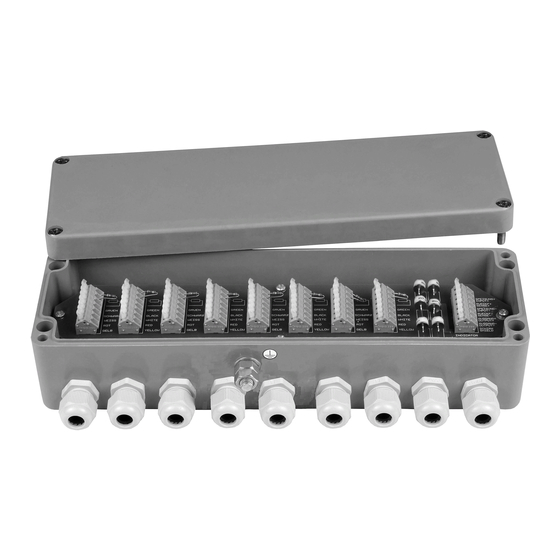
The Polyester junction box is designed for the parallel connection of load cells. There are 4 different types: Type No. of load cells Housing size Inputs Output KPF-4 up to 4 100 x 320 x 81 mm 4x M16 or 4x M12 1x M16 KPF-6... -
Page 5: Load Cell Cable Connection
ABLE ONNECTION Only the cable gland nut (see (1) in fig.1) must be loosened. The bottom part of the cable gland must remain tightened. It is absolute necessary to check all the bottom parts of the cable glands for a firm seat in the housing! Then you have to feed the load cell cable through the cable gland unless the shrink tube has fully disappeared in the box, because sealing and strain relief must be done at the cable and not at the shrink tube. -
Page 6: Corner Correction At Scales With Flintec Load Cells
LINTEC ELLS Flintec load cells are manufactured with rather tight tolerances, so in most cases an additional corner correction is not required. The best conditions are achieved if you use load cells of the same class (Designation is done with capital letters A to I on the load cell package besides the type label). -
Page 7: Summary Of Important Service Hints
UMMARY OF MPORTANT ERVICE INTS At each re-calibration or repair following checks or actions have to be done: 1. All bottom parts of the cable glands are sealed to the housing with some gasket. You have to check the existence and the condition of these gaskets, the gaskets have to be replaced if required. 2. -
Page 8: Service Material
ERVICE MATERIAL Service kit no.1 Article no.: 5200-U1 for load cells with maximum capacity above 30 t with ring spanner Parts list: Description Article no. Quantity KP cable gland M16 x 1,5, clamping range 6.5 – 9 mm 000163 9 pcs. Silicone cover sealing (red) 10090 1 pc.