
Related Manuals for Jetter JHN Series

Summary of Contents for Jetter JHN Series
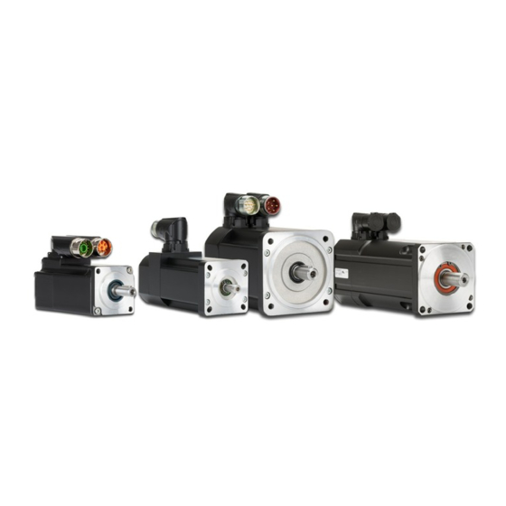
- Page 1 Installation Manual JHN, JHQ and JL - Servo Motors 60881738 We automate your success.
- Page 2 In the case of modifications, further developments or enhancements to products shipped in the past, a revised document will be supplied only if required by law, or deemed appropriate by Jetter AG. Jetter AG shall not be liable for errors in form or content, or for missing updates, as well as for damages or disadvantages resulting from such failure.
- Page 3 Servo motors Introduction Address How to contact us: Jetter AG Graeterstrasse 2 71642 Ludwigsburg, Germany Germany Phone - Switchboard: +49 7141 2550-0 Phone - Sales: +49 7141 2550-433 Phone - Technical Hotline: +49 7141 2550-444 Fax - Sales: +49 7141 2550-484 E-mail - Sales: sales@jetter.de...
-
Page 4: Hazard Levels
Safety information is classified into the following hazard levels: Hazard level Consequences Probability DANGER Death/severe injury (irreversible) The hazard is imminent. WARNING Death/severe injury (irreversible) Potential occurrence CAUTION Slight injury (reversible) Potential occurrence NOTICE Material damage Potential occurrence Jetter AG... -
Page 5: Table Of Contents
Electrical installation - Wiring description for 2-cable technology ..........30 Electrical installation - Wiring description for 1-cable technology ..........37 Instructions on EMC ........................40 Overview: Product-specific documentation related to Jetter AG motion systems ....... 41 Overview: General product documentation and tools ..............42 Jetter AG... -
Page 7: Introduction
This document is not subject to any updating service. An overview of Jetter Drive Technology related product documentation and where to find it is described in this document, see Overview of Jetter Drive Technology Product Documentation (see page 41) An overview of cross-product documentation and tools and where to find them is described in this document, see Overview of Cross-Product Documentation and Tools (see page 42). - Page 8 For protection against impacts and shocks, transport must take place in the original packaging. In case of damaged packaging inspect the device for any visible damage, and immediately inform your freight forwarder and Jetter AG of the damage caused during shipment.
-
Page 9: Basic Safety Instructions
Use only shielded signal and power lines. Observe the instructions of the inverter manufacturer for EMC-compliant installation. The servomotors may only be put into operation after the EMC installation of the complete system. Jetter AG... - Page 10 The servomotor is not intended for direct connection to the three-phase mains. Direct connection to the mains will result in its destruction. They have explicitly been designed for being torque, speed, and/or position controlled by specific servo amplifiers, such as the JetMove series by Jetter AG. Jetter AG...
-
Page 11: Residual Dangers And Protective Measures - Motors
Never pull the motor connector while the motor is energized. Do not disconnect any connectors on the servo amplifier and the control unit while higher currents are flowing. Jetter AG... - Page 12 Operational electromagnetic fields caused by the drive! Electric, magnetic and electromagnetic fields pose a particular hazard to people with pacemakers, implants or similar devices. You must not be in the immediate vicinity of the drive if you belong to the above group of persons. Jetter AG...
- Page 13 Hanging loads can fall because the holding brakes installed in the motor are not functionally safe. If the load hits you, you may be injured or killed. Functional safety can only be achieved with an additional external mechanical brake. Jetter AG...
-
Page 14: Scope Of Delivery
Mount a power output element or the yellow or black protective bracket for the feather key which comes with new motors before operating a motor. Wear goggles. Jetter AG... -
Page 15: Nameplate, Identification
The operating conditions must correspond to the data on the nameplate. Information for the The nameplate contains important information about the motor. If you wish to hotline contact the hotline of Jetter AG regarding a motor, please have the following information ready: Type designation ... - Page 16 The nameplate with UL and ATEX certification marks is attached to the motor with UL and ATEX and to the outer carton after successful UL and ATEX certification: approval This nameplate with UL and ATEX certification marks is attached to the motor on the center right: Jetter AG...
- Page 17 Continuous stall current [A] 1.03 Rated current [A] 3000 Rated speed [RPM] 3000 Winding supply voltage [VDC] 565 V Brake Brake DC 24 V 0.34A Number of motor poles Class Insulation class Tamb Ambient temperature 40 °C Degree of protection IP65 Jetter AG...
- Page 18 Type designation For more information on the type designation refer to the type code. A detailed description of this is given in the User Manual of the servo motors. Servomotoren | Jetter - We automate your success https://www.jetter.de/en/downloads/motion-systems/servo-motors.html Jetter AG...
-
Page 19: Place Of Installation, Ambient Conditions
The motor must not be exposed to rain or water jets. Therefore, do not use a steam jet or other such devices to clean the motor. Corrosive or contaminated The motor can be damaged in corrosive or surrounding area contaminated atmosphere. Jetter AG... - Page 20 When using a motor in an area with potentially explosive atmosphere, it must have an ATEX approval corresponding to the respective protection zone. Jetter servo amplifiers do not have ATEX approval and must therefore not be installed in hazardous areas. Caution when assuming The servo motors comply with the degree of protection IP65.
-
Page 21: Mechanical Installation
The installation location must be free from conductive and corrosive substances. For encapsulated installation, please consult the application department of Jetter AG. Mechanical equipment, tools NOTICE Avoid damage to the servomotor! If not handled properly, the servo motor can be damaged. - Page 22 65 °C during operation. Higher temperatures require a derating. For derating tables in case of operating the motor at higher temperatures, please turn to the motor catalog of Jetter AG. Integrate the thermistor of the motor into the monitoring system of ...
- Page 23 Prior to installing the motor, check it for possible damages in transit or storage. Please do notify Jetter AG without delay of possibly damaged mechanical equipment, as well as of corrosion damages to shaft or flange. If there is a brake, release it first. Try to turn the rotor by hand; it must react easily.
- Page 24 The rated data of the motor are reached as long as the flange temperature does not exceed 65 °C during operation. In order to remove gears, pulleys etc. please use a pulling device. Number Description Spacer screw Jetter AG...
-
Page 25: Electrical Installation - Hazards
Our motors comply with insulation class F. Thus, the insulating materials of the motor are designed for a maximum temperature of 155 °C. According to the ATEX directive, the temperature must therefore not exceed 155 °C. Jetter AG... - Page 26 Higher temperatures require a derating. Derating tables for operating the motors at higher temperatures can be found in the User Manual for servomotors by Jetter AG. Allow the motor to cool down for some time before you start working on it, e.g. to carry out maintenance jobs.
- Page 27 Observe the degree of protection at installing the motor! If an incorrect degree of protection is assumed, personal injury and damage to property may occur. Install the motor with the degree of protection required for the application. Protect the motor from harmful environmental influences. Jetter AG...
-
Page 28: Connections - New Terminology, Important Notes On Motor Connections And Wiring
Please do also observe the ambient conditions, the mode of installation and the local regulations. Note on the cables You can either order prefabricated cables from Jetter AG or opt for self-made cables. Note on the JL1 motor and some JHN2 motors: In the order reference, the length of the cables is specified in meters, e.g. - Page 29 Servo motors Connections – New terminology, important notes Power and encoder You can order the appropriate power and encoder mating connector from mating connectors Jetter AG. Jetter AG...
-
Page 30: Electrical Installation - Wiring Description For 2-Cable Technology
Electrical installation - Wiring description for 2-cable technology JL1 motor, variant 1 Jetter AG prefers the use of variants 2 or 3 to variant 1. (electrical connection A few motors of the JHN2 series also have the electrical connection S3-x.xx. - Page 31 The motor has two cable glands with cables for the power and encoder cables. The cable length must be specified in the order according to the type designation S4-x.xx in meters. The ends of the cables are fitted with connectors as shown in the figure below: Jetter AG...
- Page 32 R2L (exciter winding-) Th1 (PTC) Th2 (PTC) Plug connector M23 (with thread) Housing The outer shield is connected to the connector housing. Suitable cables for these connectors can also be found in the Industrial Automation Catalog, Products and Services. Jetter AG...
- Page 33 R2 (exciter winding-) Green, 12-pole, pins Th1 (PTC) Th2 (PTC) Y-Tec connector Housing The outer shield is connected to the connector housing. Suitable cables for these connectors can also be found in the Industrial Automation Catalog, Products and Services. Jetter AG...
- Page 34 On the JM-2xx, pins 12 and 9 in the encoder connector must be jumpered. A 9-pin Sub-D connector must be fitted at the other end of the cable. Suitable cables for these connectors can also be found in the Industrial Automation Catalog, Products and Services. Jetter AG...
- Page 35 The following table shows the pinout of the power connector, size 1.5 (M40 x 1.5): Front view Signal Phase 1 Phase 2 Phase 3 PE conductor 6-pole, pins Brake+ Brake- Housing The outer shield is connected to the connector housing. Plug connector M40 (with thread) Jetter AG...
- Page 36 On the JM-2xx, pins 12 and 9 in the encoder connector must be jumpered. A 9-pin Sub-D connector must be fitted at the other end of the cable. Suitable cables for these connectors can also be found in the Industrial Automation Catalog, Products and Services. Jetter AG...
-
Page 37: Electrical Installation - Wiring Description For 1-Cable Technology
Avoid contact between the DSL shield and the I-Tec all-over shield. Attach the DSL shielding to the motor (pin 5) and to the respective pin of the servo amplifier. Housing Place the all-over shielding and the brake shielding on the connector housing. Jetter AG... - Page 38 Avoid contact between the DSL shield and the all-over shield. Attach the DSL shielding to the motor (pin L) and to the respective pin of the servo amplifier. Housing Place the all-over shielding and the brake shielding on the connector housing. Jetter AG...
- Page 39 Avoid contact between the DSL shield and the all-over shield. Connector Attach the DSL shielding to the motor (pin 9) and to the respective pin of the servo amplifier. Housing Place the all-over shielding and the brake shielding on the connector housing. Jetter AG...
-
Page 40: Instructions On Emc
Downloading Application You can download Application Note 016 EMC-Compatible Installation of Note 016 Electric Cabinets from the Jetter AG homepage http://www.jetter.de. In order to download Application Note 016, browse the following path: Downloads - Product-independent Documentation - Application Notes. Jetter AG... -
Page 41: Overview: Product-Specific Documentation Related To Jetter Ag Motion Systems
Servo motors Product-specific documentation related to Jetter AG motion systems Overview: Product-specific documentation related to Jetter AG motion systems Jetter motors and drives Document specification Content Format Storage location Motor User Manual Engineering/selecting the *.docx, On the Jetter homepage under motor *.pdf, *.html... -
Page 42: Overview: General Product Documentation And Tools
- Application Notes installation components, wiring and shielding in the control cabinet User manuals Peripherals *.docx, On the Jetter AG homepage for *.pdf, *.html download Engineering and commissioning tools Document specification Content Format Storage location JetSym software... - Page 44 Jetter AG Graeterstrasse 2 71642 Ludwigsburg | Germany Phone +49 7141 2550-0 Fax +49 7141 2550-425 info@jetter.de www.jetter.de We automate your success.
Need help?
Do you have a question about the JHN Series and is the answer not in the manual?
Questions and answers