
Related Manuals for Greyline AVFM 5.0

Summary of Contents for Greyline AVFM 5.0
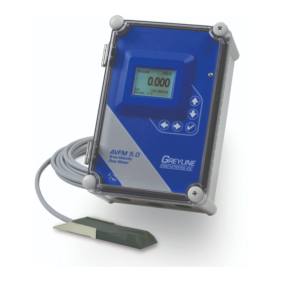
- Page 1 USER'S GUIDE Installation & Operation Instructions Area-Velocity Flow Meter Model AVFM 5.0 Manual Series A.2.3...
- Page 2 Note: This page has been left blank intentionally.
-
Page 3: Table Of Contents
AVFM 5.0 Area-Velocity Flow Meter INDEX CONNECTIONS ....................4 FUNCTION TEST ....................4 KEYPAD SYSTEM.................... 6 CALIBRATION MENU ..................7 ICONS......................... 8 MESSAGE ICON ....................9 STATUS......................9 PASSWORD..................... 10 UNITS/MODE ....................11 CALIBRATION....................12 RELAY PARAMETERS .................. 16 SPECIAL FUNCTIONS ................... 17 INSTALLATION - SENSOR LOCATION ............ -
Page 4: Connections
FUNCTION TEST: Connect the sensor to the sensor terminals as shown on next page, then apply power. Allow 30 seconds for the AVFM 5.0 to initialize. A. Place QZ02L sensor (flat to the bottom) in a bucket of water about 6” deep and select... - Page 5 AVFM 5.0 Area-Velocity Flow Meter CONNECTIONS Page 5...
-
Page 6: Keypad System
AVFM 5.0 Area-Velocity Flow Meter KEYPAD SYSTEM The AVFM 5.0 uses a menu system. Arrows show the four directions to leave a menu box. Pressing a corresponding keypad arrow will move to the next item in the direction shown. Move the cursor (underline) under numerals and increase or decrease numerals with the ... -
Page 7: Calibration Menu
AVFM 5.0 Area-Velocity Flow Meter CALIBRATION MENU Page 7... -
Page 8: Icons
AVFM 5.0 Area-Velocity Flow Meter ICONS Page 8... -
Page 9: Message Icon
The main display shows the units selected from the Units/Mode menu, Flow or Velocity rate being measured, TOTALIZER and RELAY states. The AVFM 5.0 will start-up with this display. MESSAGE ICON Press from the main display to view temperature measurement, status of the data logger and error/warning messages provided by the instrument. -
Page 10: Password
AVFM 5.0 Area-Velocity Flow Meter 24 HR LOG (Data Logging option only) Press from the MAIN display to view a formatted flow report from instruments with a built-in data logger. Press to pan through Level Velocity Flow summaries. Press to scroll down one day or repeatedly to scroll to a specific date. -
Page 11: Units/Mode
AVFM 5.0 Area-Velocity Flow Meter UNITS/MODE press the and then the or to select Mode From Flow Velocity . Flow mode displays the flow rate in engineering units (e.g. gpm, litres/sec, Level etc.) Press the to store your selection then the to the next menu item. -
Page 12: Calibration
AVFM 5.0 Area-Velocity Flow Meter CALIBRATION Press to and to enter. Use or to position before each Calibration menu item and to enter. When settings are completed press to store and return to the Calibration menu. - Page 13 AVFM 5.0 Area-Velocity Flow Meter Optional for QZ02L-A type sensor. Press and enter an Lvl Offset offset to level measurement. Set to 0.00 when sensor mounted on floor of channel. When sensor is mounted above the floor of the channel enter the distance between channel floor and bottom of sensor.
- Page 14 AVFM 5.0 Area-Velocity Flow Meter CHANNEL SETUP Round Select Round for open pipes. Set Max Height to the inner diameter of the pipe. Select for rectangular channels. Enter the channel Rectangle Rectangle width. Select for trapezoidal shaped channels. Specify the...
- Page 15 AVFM 5.0 Area-Velocity Flow Meter CUSTOM CHANNELS Reset Data Old data MUST be removed before entering data for a new channel. Press then press to and press to clear old data. Enter the maximum height of the channel.
-
Page 16: Relay Parameters
AVFM 5.0 Area-Velocity Flow Meter RELAY PARAMETERS Press and or to select a relay (2 relays are standard, 4 Relay additional are optional). Press or to select Function Pulse Flow Velocity Level Flow Position the cursor under the numerals and press or to set digits to the relay set point. -
Page 17: Special Functions
AVFM 5.0 Area-Velocity Flow Meter DATA LOGGING (OPTIONAL) Refer to Options section of this manual. SPECIAL FUNCTIONS Select Language English French Spanish Select 4-20mA or 0-5V mode for the analog output. Analog Out Select for continuous Backlight High Medium backlight. - Page 18 AVFM 5.0 Area-Velocity Flow Meter SIMULATION Exercises the 4-20mA (0-5V) outputs, digital display and control relays. and press to simulate maximum Flow, Level and Test Select Maximum Velocity and to output 20mA (5V) to the analog channels. and press to simulate minimum Flow, Level and...
-
Page 19: Installation - Sensor Location
2. For best results flow should be evenly distributed across the channel and relatively free of turbulence. (The AVFM 5.0 is very effective at averaging level and velocity readings in turbulent conditions, but best accuracy and response time is achieved with evenly distributed flow.) 3. - Page 20 AVFM 5.0 Area-Velocity Flow Meter Page 20...
- Page 21 AVFM 5.0 Area-Velocity Flow Meter OPTIONAL PIPE BAND MOUNTING WITH QZ02L SENSOR Install the stainless steel pipe band with the sensor mounting bracket at the invert (bottom) of the pipe. Ensure that the sensor bracket is parallel to the water surface (check with a level).
- Page 22 AVFM 5.0 Area-Velocity Flow Meter OPTIONAL PZ15-LP LEVEL SENSOR MOUNTING Mount the PZ15-LP non-contacting ultrasonic level sensor in an unobstructed position at least 8” (203.2 mm) above the high water level. Install the stainless steel mounting bracket in a horizontal position (check with a level) and then insert the PZ15-LP sensor.
-
Page 23: Enclosure Installation
AVFM 5.0 Area-Velocity Flow Meter ENCLOSURE INSTALLATION Locate the enclosure within 20 ft (6 m) of the sensor (up to 500 ft -150 m optional). The enclosure can be wall mounted with the four mounting screws (included) or panel mounted with Option PM Panel Mount kit from Greyline Instruments. - Page 24 AVFM 5.0 Area-Velocity Flow Meter FUSE REPLACEMENT 1. Turn OFF power. 2. Loosen cover screw and open. 3. Remove power module. 4. Locate fuse on Power Board. 5. Replace fuse with 2 AMP/ 250V, 5 x 20mm fuse. 6. Reinstall power module into chassis.
-
Page 25: Field Troubleshooting
AVFM 5.0 Area-Velocity Flow Meter FIELD TROUBLESHOOTING The AVFM 5.0 uses an ultrasonic level sensor to determine channel AREA and an ultrasonic Doppler sensor to measure flow VELOCITY. The QZ02L sensor combines both sensors in one housing. An optional configuration uses the PZ15-LP “down-looking” level sensor and a QZ02L-DP velocity sensor. - Page 26 AVFM 5.0 Area-Velocity Flow Meter SENSOR CABLE RESISTANCE TEST Unplug the green sensor terminal from the Doppler board and connect the sensor wires as shown. With a multimeter, perform resistance checks for each set of wires. One single loose terminal may cause false readings.
-
Page 27: Applications Hotline
AVFM 5.0 Area-Velocity Flow Meter APPLICATIONS HOTLINE For applications assistance, advice or information on any Greyline Instrument contact your Sales Representative, write to Greyline or phone the Applications Hotline below: United States: Tel: 315-788-9500 Fax: 315-764-0419 Canada: Tel: 613-938-8956 Fax: 613-938-4857... -
Page 28: Product Return Procedure
Instruments may be returned to Greyline for service or warranty repair. Obtain an RMA Number from Greyline - Before shipping a product to the factory please contact Greyline by telephone, fax or email to obtain an RMA number (Returned Merchandise Authorization). This ensures fast service and correct billing or credit. -
Page 29: Area-Velocity Flow Data Sheet
AVFM 5.0 Area-Velocity Flow Meter AREA-VELOCITY FLOW DATA SHEET Page 29... - Page 30 Greyline will replace or repair, free of charge, any Greyline product if it has been proven to be defective within the warranty period. This warranty does not cover any expenses incurred in the removal and re-installation of the product.
-
Page 31: Appendix A - Options
EXTRA SENSOR CABLE (OPTION VXC) Each Greyline AVFM 5.0 flow meter includes 26.25 ft. (8 m), 50 ft. (15 m) or 100 ft. (30 m) tri-coaxial sensor cable. This cable is shielded from electrical interference and is watertight with a polyurethane jacket. - Page 32 AVFM 5.0 Area-Velocity Flow Meter COAXIAL CABLE PREPARATION VXC Doppler sensor cable can be cut and spliced up to a maximum length of 500 ft (152 m). Cable ends must be prepared as illustrated below. Page 32...
- Page 33 AVFM 5.0 Area-Velocity Flow Meter JUNCTION BOX - OPTION JB2X & JB4X NEMA4X (IP66) polycarbonate Junction Box with terminal strips is available from Greyline Instruments. Includes compression fittings for watertight coaxial cable entries. Page 33...
- Page 34 AVFM 5.0 Area-Velocity Flow Meter SS PIPE MOUNTING BAND – OPTION VSJ Page 34...
- Page 35 Class II, Groups E,F,G Class III Intrinsic Safety Barriers may be ordered with the Greyline instrument and are supplied mounted in the Greyline instrument enclosure. Replacement barrier fuses (Part No. ISB- 011239) may be purchased separately. The instrument enclosure containing the Intrinsic Safety Barriers must be installed in a non- hazardous location.
- Page 36 AVFM 5.0 Area-Velocity Flow Meter Page 36...
- Page 37 AVFM 5.0 Area-Velocity Flow Meter ENCLOSURE HEATER AND THERMOSTAT - Option TH Instruments can be factory-equipped with an Enclosure Heater and Thermostat or the module can be customer-installed. The Thermostat is factory set to turn ON at 40°F (4.5°C) and OFF at 60°F (15.5°C).
- Page 38 AVFM 5.0 Area-Velocity Flow Meter POWER INPUT OPTION 9-32VDC AVFM 5.0 Flow Meters may be ordered factory-configured for 9-32VDC power input. CONNECTIONS: POWER INPUT: Connect 9-32VDC to the + and - terminals. The Power Input GND terminal must be connected to the nearest Ground pole. A 1-amp fuse in line is recommended.
-
Page 39: Data Logging (Optional)
Mode Interval applied to the log file. View 24-hr formatted Reports on the AVFM 5.0 display. Press from the main display to view a formatted flow report from instruments with a built-in data logger. Press to pan through summaries. - Page 40 Older files can be erased or moved from the flash memory drive or a new memory drive can be used. OPENING LOG FILES Install Greyline Logger on your PC or laptop. Refer to the Help menu in the program for detailed instructions. Select File/Open/Instrument Log (.log) to open the log file from your USB flash drive.
-
Page 41: Specifications
AVFM 5.0 Area-Velocity Flow Meter SPECIFICATIONS Electronics Enclosure: NEMA4X (IP 66), watertight and dust tight, polycarbonate with clear, shatterproof hinged Lexan cover Accuracy: Level: ± 0.25% of Range Velocity: ± 2% of Reading. Requires solids or bubbles minimum size of 100 microns, minimum concentration 75 ppm. - Page 42 AVFM 5.0 Area-Velocity Flow Meter Velocity/Level Sensor QZ02L Minimum Velocity: 0.1 ft/sec (0.03 m/sec) Maximum Velocity: 20 ft/sec (6.2 m/sec) [reverse flow to -5 ft/sec (-1.5 m/sec)] Minimum Head: 1 in. (25.4 mm) Maximum Head: 16 ft. (4.88 m) Operating Temperature: 5 to 175°F (-15 to 80°C)
- Page 43 AVFM 5.0 Area-Velocity Flow Meter Optional (Velocity only) Sensor QZ02L-DP Minimum Velocity: 0.1 ft/sec (0.03 m/sec) Maximum Velocity: 20 ft/sec (6.2 m/sec) [reverse flow to -5 ft/sec (-1.5 m/sec)] Operating Temperature: 5 to 150°F (-15 to 65°C) Exposed Materials: PVC, epoxy resin, polyurethane, ultem Sensor Cable: 26.25 ft (8 m) submersible polyurethane jacket, shielded, 3-coaxial...
- Page 44 AVFM 5.0 Area-Velocity Flow Meter Dual Non-Contacting Sensor Configuration Page 44...
- Page 45 AVFM 5.0 Area-Velocity Flow Meter CONNECTIONS Dual Sensor Configuration Page 45...
- Page 46 AVFM 5.0 Area-Velocity Flow Meter CALIBRATION Non Contacting Level Sensor Configuration Press to and to enter. Use or to position Calibration before each menu item and to enter. When settings are completed press to store and return to the Calibration menu.
- Page 47 AVFM 5.0 Area-Velocity Flow Meter Only for PZxx type sensor. Press and enter the max level MinRg (distance from the PZxx sensor to the max water level). Press and enter a minimum velocity cutoff. Forward and Min Vel...
- Page 48 AVFM 5.0 Area-Velocity Flow Meter PZxx FLANGE SENSOR MOUNTING METHODS IN ROUND PIPES Notes: 1. Use the ¾” NPT “Isolation Coupling” supplied and hand tighten only. Do not clamp sensor body or stem. 2. Do not mount sensor or cover flange in direct sunlight.
- Page 49 Warm temperatures, moisture and vibration will accelerate this process. Dow Corning Silicone Compound #4 as supplied with the AVFM 5.0 (and available from Greyline Instruments) is recommended for semi-permanent installations. Page 49...
- Page 50 The objective of site preparation is to eliminate any discontinuity between the sensor and the pipe wall, which would prevent acoustical coupling. A PC4 Sensor Mounting Kit is supplied with each Greyline flow meter. It includes recommended coupling compound in a plastic applicator and a stainless steel mounting bracket with adjustable pipe straps.
Need help?
Do you have a question about the AVFM 5.0 and is the answer not in the manual?
Questions and answers