Table of Contents
Advertisement
Quick Links
Advertisement
Table of Contents

Related Manuals for EGAmaster EgaTronic COD.58515

Summary of Contents for EGAmaster EgaTronic COD.58515
- Page 1 OPERATING INSTRUCTIONS MULTIMETER COD.58515 GUARANTEE ......21...
-
Page 2: Unpacking Inspection
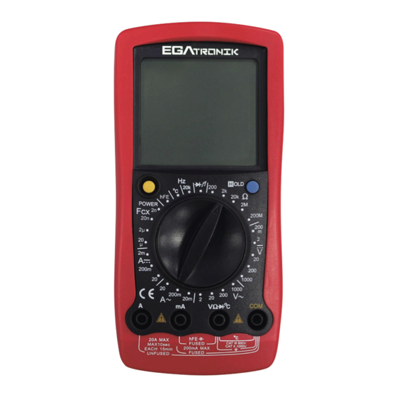
ENGLISH OVERVIEW To avoid electric shock or personal injury, read the “Safety Information” and “Rules for Safety Operation”carefully before using the Meter. Digital Multimeters COD.58515 (hereafter referred to as “the Meter”) is 4 1/2 digits with ex-large LCD, steady operations, fashionable structure and highly reliable hand-held measuring instrument. -
Page 3: Rules For Safe Operation
CAT. III: Distribution level, fixed installation, with smaller transient overvoltages than CAT. IV Use the Meter only as specified in this operating manual, otherwise the protection provided by the Meter may be impaired. In this manual, a Warning identifies conditions and actions that pose hazards to the user, or may damage the Meter or the equipment under test. -
Page 4: International Electrical Symbols
• Soft cloth and mild detergent should be used to clean the surface of the Meter when servicing. No abrasive and solvent should be used to prevent the surface of the Meter from corrosion, damage and accident. • The Meter is suitable for indoor use. •... -
Page 5: Rotary Switch
ROTARY SWITCH Below table indicated for information about the rotary switch positions. Rotary Switch Position Function DC voltage measurement AC voltage measurement Transistor Test AC Current Measurement DC Current Measurement Capacitance Test ºC Temperature Measurement Frequency Measurement Diode test Continuity test Ω... - Page 6 Nº Symbol Meaning The battery is low. Warning: To avoid false readings, replace the battery as soon as the battery indicator appears. Warning Symbol Indicator for AC voltage or current. The displayed value is the mean value. Indicates negative reading Test of diode The continuity buzzer is on Date hold is active...
-
Page 7: Measurement Operation
MEASUREMENT OPERATION A. DC AND AC VOLTAGE MEASUREMENT (see figure 3) (figure 3) Warning! To avoid harms to you or damages to the Meter from electric shock, never attempt to measure voltages higher than 1000 or 1000V rms although readings may be obtained. The DC Voltage ranges are: 200mV 2V, 20V, 200V and 1000V. - Page 8 B. DC AND AC CURRENT MEASUREMENT (see figure 4) (figure 4) Warning! Never attempt an in-circuit current measurement where the open circuit voltage between terminals and ground is greater than 60V DC or 30V rms in AC. If the fuse burns out during measurement, the Meter may be damaged or the operator himself may be hurt.
- Page 9 Note • l If the value of current to be measured is unknown, use the maximum measurement position, and reduce the range step by step until a satisfactory reading is obtained. • l For safety sake, the measuring time for high current should be less than 10 seconds and the interval time between 2 measurements should be greater than 15 minutes.
- Page 10 D. MEASURING DIODES AND CONTINUITY (see figure 6) (figure 6) Warning! To avoid damage to the Meter or to the equipement under test, disconnect circuit porwer and discharge all high-voltage capacitors befire measuring diodes. To avoid harms to you, never attempt to input voltages higher than 60V DC or 30V rms in AC.
- Page 11 Testing for Continuity To test for continuity, connect the Meter as below: 1. Insert the red test lead intoV terminal and the black test lead into the COM terminal. 2. Set the rotary switch to 3. Connect the test leads across with the object being measured. ≤70Ω.
- Page 12 F. TEMPERATURE MEASUREMENT (see figure 8) (figure 8) Warning! To avoid harm to you or damages to the Meter, never attempt to measure voltages higher than 60V in DC or 30V rms in AC although readings may be obtained. During testing, the operating temperature must be within 18-23o C, otherwise the obtained reading may not be correct especially measuring low temperature.
- Page 13 G. CAPACITANCE MEASUREMENT (see figure 9) (figure 9) Warning! To avoid damage to the Meter or to the equipment under test, disconnect circuit power and discharge all high-voltage capacitors before measuring capacitance.Use the DC voltage function to confirm that the capacitor is discharged. To avoid harms to you, never attempt to input voltages higher than 60V DC or 30V rms µ...
- Page 14 • It is normal to take a longer time when testing a high capacitor value. • For testing the capacitor with polarity, connect the red clip or red test lead to anode and black clip or black test lead to cathode. •...
- Page 15 GENERAL SPECIFICATIONS • Maximum Voltage between any Terminals and grounding: Refer to different range input protection voltage. Fused Protections for mA Input Terminal. • CE Version: 0.5A, 250V fast type, f 5x20mm. VΩºC input jack’s fuse: 0.63A, 250V fast type, ɸ5x20mm, to be used on capacitance, temperature and transistor testing input protection.
- Page 16 A. DC Voltaje Range Resolution Accuracy Overload Protection 200mV 0.01mV ±(0.05%+3) 250V DC / V AC 0.0001V 0.001V ±(0.1%+3) 1000V rms 200V 0.01V 1000V 0.1V ±(0.15%+5) Ω Remarks: Input Impedance: approx. 10M B. AC Voltaje Range Resolution Accuracy Overload Protection 0.0001V 0.001V ±(0.5%+10)
- Page 17 E. Resistance Test Range Resolution Accuracy Overload Protection ±(0.5%+10) + Test Ω Ω Lead Short Circut 0.01 Resistance Ω Ω 0.0001k 250V rms Ω Ω ±(0.3%+1) 0.001k Ω Ω 0.0001M ±5% (reading-1000) Ω Ω 200M 0.01M + 10 Remarks: • Ω...
-
Page 18: Maintenance
I. Capacitance Range Resolution Accuracy Overload Protection 0.0001nF ±(3%+40) 20nF 0.001nF 250V rms µF µF 0.0001 ±(4%+10) µF µF 0.001 Remarks: • 40mVrms. Testing signal is approx.: 40Hz J. Transistor test Range Resolution Testing Conditions Overload Protection µA lbo 10 250V rms Vce 2.8V Remarks:... - Page 19 B. REPLACING THE FUSES (see figure 10) (figure 10) Warning To avoid electrical shock or arc blast, or personal injury or damage to the Meter, use specified fuses ONLY in accordance with the following procedure. To replace the Meter’s fuse: 1.
- Page 20 C. REPLACING THE BATTERY (see figure 10) Warning To avoid false readings, which could lead to possible electric shock or personal injury, replace the battery as soon as the battery indicator “ ” appears. To replace the Meter’s battery: 1. Turn the Meter power off and remove all connections from the terminals. 2.
Need help?
Do you have a question about the EgaTronic COD.58515 and is the answer not in the manual?
Questions and answers