Table of Contents
Advertisement
Quick Links
Advertisement
Table of Contents

Related Manuals for Rehau RE.GUARD

Summary of Contents for Rehau RE.GUARD
- Page 1 RE.GUARD WATER CONTROL DEVICE Installation and operating instructions...
- Page 2 These ‘RE.GUARD Water Control Device’ installation and operating instructions are valid from July 2020. With its publication the previous Technical Information 410600 (dated December 2019) becomes invalid. Our current technical documents can be downloaded from www.rehau.com/ti or via the QR code.
-
Page 3: Table Of Contents
Operating principle Range of application Controls and indicators Accessories 2.4.1 RE.HUB gateway 2.4.2 RE.GUARD water sensor 2.4.3 Other accessories RE.GUARD water control device technical data Installation Delivery contents Transport and storage Networking components 3.3.1 Networking prior to installation ® 3.3.2 Z-Wave –... - Page 4 Unpairing device from Z-Wave (exclusion) 5.1.3 Closing/opening the valve manually 5.1.4 Acknowledging a burst pipe (macro leak) 5.1.5 Acknowledging drip leak (micro leak) 5.1.6 Acknowledging detected water spillage (via optional RE.GUARD water sensor) 5.1.7 Activating/deactivating custom mode 5.1.8 Deactivation 5.1.9 Reactivation 5.1.10 Resetting the device to factory settings Operation using the RE.GUARD app...
- Page 5 ® Z-wave : relevant data Associations Notifications Konfigurationsparameter Z-Wave ® Command classes Appendix Table of Threshold Values...
-
Page 6: Information And Safety Instructions
These installation instructions are valid for Germany. Intended use Pictograms and logos The RE.GUARD water control device may only The following pictograms and logos are used in be installed and operated as described in these these instructions: instructions. Compliance with these instructions is part of intended use. -
Page 7: Safety Instructions
REHAU. The contact instructions. details for your region or country can be found on the back cover page. -
Page 8: Product Description
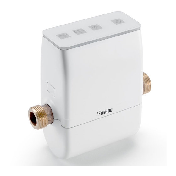
Fig. 2-1 RE.GUARD water control device prevent the occurrence of leaks itself. However, The RE.GUARD water control device is a device through correctly setting the parameters and to install in the drinking water supply pipe, which thresholds, based on the respective appliances... -
Page 9: Range Of Application
1.0 MPa (10 bar). If the network through regular maintenance. pressure is higher than 1.0 MPa (10 bar), the RE.GUARD water control device must only be Expansion vessels installed in the drinking operated downstream after a pressure reducer water system, e.g. -
Page 10: Controls And Indicators
RE.GUARD water control device. historical data, etc.) which can be accessed via Extended functionality including adjusting the the RE.GUARD app (Android Version 7 and above thresholds, setting notifications, schedules and iOS Version 11 and above). and other actions can be accessed through ®... -
Page 11: Re.guard Water Sensor
RE.GUARD water sensor include, for example, household appliances and sanitary fixtures (under the bathtub, dishwasher, washing machine etc.) Up to 10 RE.GUARD water sensors can be linked to a RE.GUARD water control device. ® Other Z-wave floor sensors or other sensors ®... -
Page 12: Re.guard Water Control Device Technical Data
RE.GUARD water control device technical data Dimensions Length of casing (excluding thread connections) 141 mm Total length of device (including thread connections) 190 mm Height of bottom edge – thread axis 76 mm Height of top edge – thread axis 113 mm... - Page 13 Product features Dimensions and connections Nominal diameter DN 20 Screw connections G1" external thread as per ISO 228 (flat-sealing) Spanner size SW27 Materials Base body Lead-free gunmetal as per DIN specification 2701 Casing Acrylonitrile styrene acrylate copolymer (ASA) Control panel Plexiglas (PMMA –...
-
Page 14: Installation
3 INSTALLATION Delivery contents The following components are included in the delivery contents of the RE.GUARD water control device: RE.GUARD Sicherheitshinweise Bezpečnostné upozornenia Safety warnings Zalecenia bezpieczeństwa Consignes de sécurité Bezbednosne napomene Indicazioni di sicurezza Sigurnosne napomene Indicaciones de seguridad... -
Page 15: Networking Components
The initial networking process between the through the RE.GUARD app. The RE.GUARD app RE.GUARD water control device and the RE.HUB runs on smartphones with Android (version 7 and gateway requires a high level of data exchange higher) and iOS (version 11 and higher). -
Page 16: Connecting To The Plumbing System
It is recommended to install the RE.GUARD water control device in the drinking water installation immediately after the domestic water meter, i.e. directly after the isolation valve with check valve,... - Page 17 In the shell construction phase, it is possible to replace the RE.GUARD water control device Expansion vessels installed in the drinking with a water meter adapter that is 190 mm in water system, e.g. in the supply to the length with G1"...
-
Page 18: Permissible Installation Positions
Horizontal installation rotated up to 90° The standard installation horizontally of the Distance x from the wall at 90° ≥ 85 mm RE.GUARD water control device is horizontal with the display facing upwards. The required wall distance x increases the further forward the device faces. - Page 19 Vertical installation Alternatively, the RE.GUARD water control device can also be installed in vertical pipe sections. ≤ 90° ≤ 90° Fig. 3-7 Vertical installation Distance x from the wall at 90° ≥ 85 mm The orientation of the device, including the...
-
Page 20: Installing The Re.guard Water Control Device
Both types of installation are described here and allow the RE.GUARD water control device to be To support the device when tightening the integrated into the drinking water network tension threaded connections, use only the wrench free. - Page 21 The water meter fittings require G1" union nuts and flat gaskets suitable for drinking water on the connection sides of RE.GUARD water control device. Cut the pipe with suitable tools. The distance ‘x’ is calculated from the selected water meter bracket incl.
- Page 22 Insert flat gaskets and engage the thread Open the mains isolation valve again. connections of the RE.GUARD water control device. Tighten the screw connections with a suitable Afterwards, flush the drinking tool (wrench or adjustable spanner) (wrench flats water installation in accordance RE.GUARD water control device: size 27).
- Page 23 The distance ‘x’ is calculated from the length distances from the wall). of the RE.GUARD water control device, which is 190 mm, as well as any other adapters required to connect to the existing piping system. Screw connections and adapters are not included...
- Page 24 Position the RE.GUARD. Chapter “3.5 Rotate the Open the mains isolation valve again. top of the housing”, page 25 describes the process of rotating the display, if necessary. Afterwards, flush the drinking water installation in accordance Watch out for the flow direction...
-
Page 25: Rotate The Top Of The Housing
Gently push the release points above the the mains supply before opening it. water connections of the RE.GUARD water control device slightly inward (max. 5mm). The top of the housing may also need to be removed to insert the batteries (emergency power mode) (see Chapter “6.2 Inserting/changing... - Page 26 Make sure that the cables are not pinched or pulled out of their terminals when sliding back the upper half. As whilst removing the top of the housing, slide down the top at a right angle to the direction of flow and installation without tilting.
-
Page 27: Power Supply
Connect to the mains supply An available socket for a type C European plug is required to securely connect the mains adapter of the RE.GUARD water control device to the power supply. Risk to life due to electric shock A water leak may occur during installation, which can lead to a short circuit or electric shock. -
Page 28: Backup Power
3.6.2 Backup power Commissioning The RE.GUARD water control device has an After installation of the RE.GUARD water control integrated battery compartment for four AA or R6 device and plugging in the mains plug, the device backup batteries (batteries are not included in the performs a self-test and is ready for use after delivery contents). -
Page 29: Operating Modes
4 OPERATING MODES Depending on the respective situation, the RE.GUARD water control device is in a specified operating mode. Alternatively, it can also be intentionally switched into another operating mode using the operating buttons on the device itself or via the app. -
Page 30: Standard Mode
RE.GUARD app. Threshold: adjusted values ‘Present’ and ‘absent’ modes ‘Present’ mode The RE.GUARD water control device is in normal ‘Absent’ mode operation. The thresholds are factory-set for the This mode can be used during absences (for average day-to-day operation. example, holidays). The shut-off criteria generally correspond to ‘present’... -
Page 31: Custom Mode
Custom mode In custom mode, the leak prevention function Display indicators/light ring on the device: of the RE.GUARD water control device is temporarily deactivated. This may be necessary if, for example, a pool is being filled or another appliance needs a higher quantity of water over... -
Page 32: Operation
5 OPERATION Operation and status indicators on the device On the device itself only basic functions can The RE.GUARD water control device has a be accessed. Extended functionality including display on top with four buttons for status adjusting the thresholds, setting notifications,... -
Page 33: Pairing Device With Z-Wave (Including/Adding)
Pairing device with Z-Wave (including/adding) Pairing must take place to integrate the Enable pairing search: ® RE.GUARD water control device into a Z-wave network. This pairing is optimised for connection to the RE.HUB gateway (see Chapter “2.4.1 RE.HUB gateway”, page 10 and the operating instructions of the RE.HUB gateway). -
Page 34: Unpairing Device From Z-Wave (Exclusion)
Unpairing device from Z-Wave (exclusion) Unpairing a device might be necessary if the Unpairing the device: RE.HUB gateway needs to be replaced or during a permanent removal of the RE.GUARD water control device (for example, when passing on the device). White... -
Page 35: Closing/Opening The Valve Manually
Closing/opening the valve manually 5.1.4 Acknowledging a burst pipe (macro leak) The RE.GUARD water control device can be closed or opened manually in two ways: If the threshold for the either the maximum running time of water, amount of water or current This action switches the device into ‘present’... -
Page 36: Acknowledging Drip Leak (Micro Leak)
The factory default settings trigger a drip leak Acknowledging alert: check every day at 3 am, but only send an alert in case of a pressure drop and the RE.GUARD water control device remains open (Option 1, factory default). It is only possible to switch to option 2 (‘close valve’) using the app. -
Page 37: Acknowledging Detected Water Spillage (Via Optional Re.guard Water Sensor)
5.1.6 Acknowledging detected water spillage (via optional RE.GUARD water sensor) If an additional RE.GUARD water sensor has Floor spillage alert: been installed and properly paired and it detects any moisture, a warning will be displayed on the RE.GUARD water control device and optionally the mains isolation valve will be closed. -
Page 38: Activating/Deactivating Custom Mode
In custom mode, the RE.GUARD water control Activating custom mode: device temporarily deactivates the leak prevention function. (See Chapter “4.4 Custom mode”, page 31). After a set time, the RE.GUARD water control Press for White White Green Flashes device automatically returns to normal operation 3 s,... -
Page 39: Deactivation
5.1.8 Deactivation Initiate deactivation Press and hold the buttons simultaneously for 6 s: When deactivated, the leak prevention function of the RE.GUARD water control device is permanently deactivated. (See Chapter ”4.5 Deactivation”, page 31). White Press White Press White Deactivation must be done in two steps: for 6 s... -
Page 40: Reactivation
5.1.9 Reactivation Initiate reactivation Press and hold the buttons simultaneously for 6 s: To return to normal mode after deactivation, the RE.GUARD water control device must be reactivated. Reactivation must be done in two steps: Yellow Press Yellow Press Yellow 1. Initiate reactivation for 6 s... -
Page 41: Resetting The Device To Factory Settings
5.1.10 Resetting the device to factory settings If the RE.GUARD water control device is being Initiate reset permanently removed form an installation (for Press and hold the buttons simultaneously for 20 s: example, passed on to someone else) or if there is a fault with the RE.HUB gateway, then it can be... -
Page 42: Operation Using The Re.guard App
Start the RE.GUARD app and follow the step-by- step instructions in the app. RE.GUARD app after the first start-up The RE.GUARD app can be used to control all functions of the REGUARD water control device and to customise settings for the relevant drinking water installation. - Page 43 ‘Settings > Water gateway. This set-up comprises: Detector’. Up to 10 RE.GUARD water sensors can be linked 1. Connect the RE.HUB gateway to a router with to a RE.GUARD water control device. a LAN cable (supplied).
-
Page 44: Screens And Navigation
Screens and navigation My home (starting page) The screen shows the current valve position, real time measurements and the RE.GUARD can also be closed and opened here. This page is the home page of the app and can be accessed by selecting the home icon on the bottom bar. -
Page 45: Adjusting Thresholds
The thresholds of 'present' and 'absent' modes device and stored there. can be set under 'Settings > Limits'. The criteria for shutting off the RE.GUARD water Adjust the 'present’ mode thresholds control device are the same as in present mode, but the thresholds should be smaller. - Page 46 The factory default settings trigger a drip leak check every day at 3 am, but only send an alert in case of a pressure drop and the RE.GUARD water control device remains open (Option1, factory default). It is possible to switch to option 2 (‘close valve’) in the app.
-
Page 47: Servicing
Inspection and maintenance - Visual inspection of the inner parts checking along the water carrying components for any The RE.GUARD water control device is a device leaks, corrosion, undesired condensation or any for drinking water installations with moving other signs of damage. - Page 48 Gently push the release points above the free of charge and anywhere where batteries water connections of the RE.GUARD water of the respective type are sold. In the case of control device slightly inward (max. 5mm). batteries that are not fully discharged, precaution must be taken against short circuiting, for example, by isolating the battery connections.
- Page 49 between the top and bottom parts does not Risk of injury exceed approx. 10 cm. The metal brackets can have sharp edges. When removing and inserting the battery compartment pay extra attention to It should be pulled straight up as avoid cutting injuries. indicated by the arrows (see above).
- Page 50 For a longer cycle than 12 months, Ensure that all cable connections lithium batteries (not rechargeable are still present. lithium batteries!) can be used instead of Cables that became loose (sensor board, conventional alkaline batteries to replace motor) can be inserted back into colour the emergency power batteries as coded terminals.
-
Page 51: Updates
RE.GUARD water Once the RE.GUARD water control device is control device and thus cause damage to connected to the mains supply, the device the function up to complete failure or performs a self-test and is ready for use after a broken housing. -
Page 52: Spare Parts
REHAU. conditions (e.g. disposal via recycling yards) must be observed. Unauthorised modifications or changes to the RE.GUARD water control device, in Dispose of the batteries properly. particular the installation and use of self- procured electrical, electronic and sensory... -
Page 53: Malfunctions
All leaks such as macro leaks (burst pipe), micro leaks (drip leaks) and detection of water on the Motor and sensor malfunction floor (via RE.GUARD water sensor) are registered as alerts and not as malfunction. Such alerts are Motor malfunction:... - Page 54 Power failure and backup power batteries Z-wave connection error fault The device will indicate a disrupted radio signal Battery level low – replacement recommended: between the RE.GUARD water control device and the RE.HUB gateway as shown below. Connection lost: White White White...
-
Page 55: Corrective Measures
Connection to RE.HUB 1. Make sure that both the RE.HUB gateway as well as the gateway lost RE.GUARD water control device are connected to the power and the mains adapters are properly plugged in and are not faulty. 2. Remove any possible sources of interference within the signal range, which may have been newly added and are too close to the equipment (at least 50 cm distance). - Page 56 (for example, the ‘AEOTEC Range Extender 6’ repeater). 5. Exclude the RE.GUARD water sensor in the app. Then, reset it to factory settings (for the procedure, see the RE.GUARD water sensor operating instructions). Afterwards, repeat the pairing process in the app.
- Page 57 Description of fault Possible corrective measures RE.GUARD water control Replace the emergency batteries (4 x AA) as described in Chapter device emergency batteries ‘6.2 replacing/inserting emergency batteries’, page 54 empty...
-
Page 58: Emergency Release (Emergency Open Function)
RE.GUARD water control device, which is cannot be undone on the device, by unplugging and plugging the mains adapter, or via the RE.GUARD app, the device has a manual ‘emergency open’ function. Gently push the release points... - Page 59 Pull the drive including the connecting cable Risk of injury upwards. Motor-operated parts can suddenly move due to battery emergency power. Remove one or more batteries from the battery compartment (see Chapter “6.2 Inserting/changing emergency batteries”, page 47) to disable emergency power. Pull the allen key out upwards.
- Page 60 10. Consult the list of faults at the end of this operating instruction as well as the app and 90° contact the installer to determine the cause of the malfunction, if necessary. 11. Once the cause has been established and rectified, reverse the emergency open and assemble the device by following the previous steps in reverse order.
-
Page 61: Wave ® : Relevant Data
® 8 Z-WAVE : RELEVANT DATA ® This device is a secure Z-wave Plus product device between the control panel and the thread ® that uses encrypted Z-wave Plus messages to connection. ® communicate with other secure Z-wave Plus ® products. -
Page 62: Notifications
Notifications Notification type Notification event Description Water (0x05) Water leak detected (0x02) A notification is sent if the threshold for flow rate, volume and time are exceeded. A notification is sent if the threshold for a pressure drop when the shut-off is closed. Water (0x05) Water pressure alarm (0x07) A notification is sent if the threshold values for... -
Page 63: Konfigurationsparameter Z-Wave
Konfigurationsparameter Z-Wave® The RE.GUARD water control device uses the following configuration parameters:... -
Page 66: Command Classes
Command classes ® The following Z-wave command classes are used for the RE.GUARD water control device: 5E - COMMAND_CLASS_ZWAVEPLUS_INFO_V2 6C - COMMAND_CLASS_SUPERVISION_V1 55 - COMMAND_CLASS_TRANSPORT_SERVICE_V2 98 - COMMAND_CLASS_SECURITY_V1 9F - COMMAND_CLASS_SECURITY_2_V1 25 - COMMAND_CLASS_SWITCH_BINARY_V1 [S0]* [S2]* 85 - COMMAND_CLASS_ASSOCIATION_V2 [S0]* [S2]*... -
Page 67: Appendix
APPENDIX Table of Threshold Values The following table shows, depending on appliances and number of persons, the threshold values examples for the 'present' mode. The ‘absent’ mode is to be adjusted depending on what is possible during this time (for example, so neighbours can still water plants when the occupier is on holiday). - Page 68 BIM@REHAU allows you to receive more than just BIM content about REHAU products and solutions quickly and easily. It benefits you and your construction projects. Stronger together BIM stands for interaction of all those involved in the project with and in a central data model.
Need help?
Do you have a question about the RE.GUARD and is the answer not in the manual?
Questions and answers