
Related Manuals for URIMAT Favorit


Summary of Contents for URIMAT Favorit
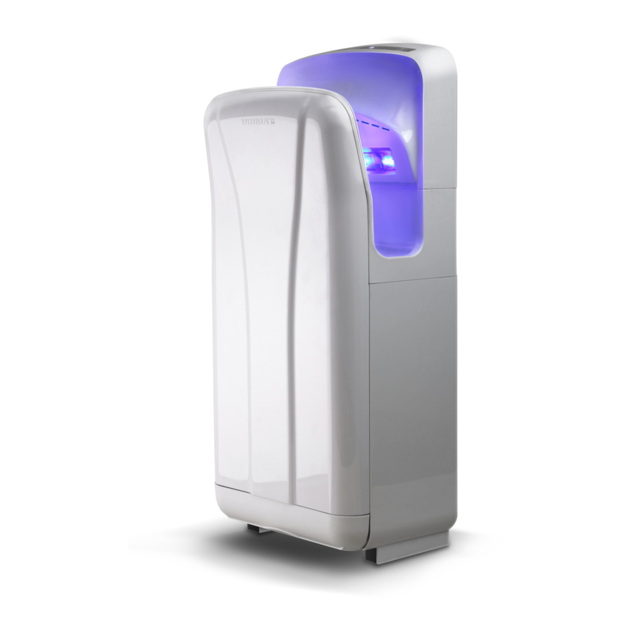
- Page 1 URIMAT Schweiz AG +41 (0)55 251 52 30 www.urimat.com Etzelstrasse 39 +41 (0)55 251 52 31 www.urimat.com CH-8934 Hombrechtikon info@urimat.com www.urimat.com URIMAT favorit Installation manual: article 37.520 REACH...
- Page 2 Rated voltage AC220V Motor Brushless DC motor Input power 1850W Induction method IR blocking Wind velocity Protection class 95m/s IPX4 Dimensions Warm air 1850W 300X220X685mm Net weight 10.5kg Cold air 750W...
- Page 3 WARN ING personal injury accidents will happen if use improperly • Do not open the front panel . otherwise, This may get an electric shock • Children forbidden hanging on the machine, Prohibited there are risk of falling. • Do not use in a wet environment,for example,near the bathroom where it may get the direct water and the places where the condensation may form.otherwise,this may cause electric shock and unit malfunction.
- Page 4 Drehzahlschalter Heizungsschalter Abdeckung Spannungsversorgung Anzeige der Trocknungszeit und Fehleranzeige Stromanzeige Anzeige Eigenkontrollsystem Bereich Händetrocknung Netzschalter Leuchtelement Ablaufschlauch Luftfilter Gerät Auffangbehälter Position Klemmkasten Montageplatte Netzkabel (hinten) Position Klemmkasten Auffangbehälter Luftfilter...
- Page 5 Usage ■ Using the Unit Stretch out both hands and insert them all the way in. The unit starts to run automatically. • Pull them out slowly, letting the air blow the water off. • Pull them out completely. ■ Seif-check indicator When a malfunction or error occurs, the seif-check indicator on the right side will either light up or flash.
- Page 6 Handle Drain tank Cover Air filter Drain tank Cover Drain tank Drain hole...
- Page 7 Motor Thermal Temperature Thermal circuit Power probe protection breakers switch switch Heaters Wiring terminal blocks Power...
- Page 8 Stromanzeige Anzeige Eigenkontrollsystem Spannungsversorgung Gerät Befestigungsschrauben Montageplatte 630mm Abstand zwischen dem Power switch Klemmkasten ohne Deckel und Fußboden Empfohlene Installationshöhe 89 cm (für Männer) 87 cm (für Frauen) Luftfilter Frontdeckel u. Befestigungsschrauben Auffangbehälter...
- Page 9 81.5 Installation screws 57.5 57.5 57.5 57.5 Installation Panel Switch box Installation hole details Unit(mm) Terminal box Drain tank Chuckhole Front panel installation Terminal box screw cover Front panel Unit Terminal box Unit cover screw Unit Upper hook Power socket Power cord Power cord Installation...
- Page 10 Unscrew here to change fuse Earth wire Power cord Terminal box Power cord Power cord retainer Terminal box Terminal box cover Terminal box cover screw Unit Unit Front panel Installation screw Drain tank...
- Page 11 Roughing efficiency (air) filter...
Need help?
Do you have a question about the Favorit and is the answer not in the manual?
Questions and answers