Advertisement
Quick Links
1
Introduction
Use this document for quick installation and setup.
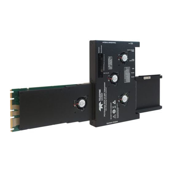
Teledyne LeCroy's PCI Express Gen4 OCP NIC 3.0 Interposer provides a quick and simple means for protocol analysis of
Gen4 OCP NIC 3.0 small form factor devices based on PCI Express (PCIe
Card, used with the Summit T4 family of Protocol Analyzers, enables PCIe bus traffic between a host backplane and Gen4
OCP NIC 3.0 form factor device to be monitored, captured, and recorded for protocol analysis. The interposer supports data
rates of 2.5 GT/s, 5.0 GT/s, 8.0 GT/s and 16.0 GT/s, side band signals such as PERST#, WAKE# and SMBus (SMBCLK,
SMBDAT). The Gen4 OCP NIC 3.0 Interposer supports link widths up to x16.
2
Components
The interposer package includes the following components:
•
PCI Express Gen4 OCP NIC 3.0 Interposer
•
DC Power Adapter (+12V @ 5A)
•
External latch bracket
Inspect the received shipping container for any damage. Unpack the container and account for each of the system
components listed on the accompanying packing list. Visually inspect each component for absence of damage.
In the event of damage, notify the shipper and Teledyne LeCroy. Retain all shipping materials for shipper's inspection.
PCI Express
Interposer
User Manual and Quick Start Guide
PCI Express Gen4 OCP NIC 3.0 Interposer
®
Gen4 OCP NIC 3.0
®
) protocols. The Gen4 OCP NIC 3.0 Interposer
•
External lever
•
User Manual and Quick Start Guide
(this document)
Advertisement

Subscribe to Our Youtube Channel
Related Manuals for Teledyne Lecroy PCI Express Gen4 OCP NIC 3.0 Interposer


Summary of Contents for Teledyne Lecroy PCI Express Gen4 OCP NIC 3.0 Interposer
- Page 1 Introduction Use this document for quick installation and setup. Teledyne LeCroy’s PCI Express Gen4 OCP NIC 3.0 Interposer provides a quick and simple means for protocol analysis of ® Gen4 OCP NIC 3.0 small form factor devices based on PCI Express (PCIe ) protocols.
- Page 2 Slide the Gen4 OCP NIC 3.0 device into the device bracket and carefully push it into it’s mating connector on the Gen4 OCP NIC 3.0 Interposer. Connect the Summit T416 Analyzer (or other compatible Teledyne LeCroy analyzer) to the interposer using two Gen4 Y cables (PE021UCA-X).
- Page 3 Configuration and other Switch Settings SW1: DUT Power Status LED on Interposer This switch connects the DUT power Indication LEDs to the bus power. It is located near teh Lane Activity LEDS. SW1: DUT Power Status LEDs LED Connected (Default) LED Disconnected Note: This switch connects the DUT power indication LEDs to the bus power.
-
Page 4: Test Points
Test Points Test Point Number Test Point Name Test Point Number Test Point Name Test Point Number Test Point Name TP-1 3.3 V HOST TP-30 RBT_ARB_IN TP-40 TP-2 12V Host TP-31 12V FROM DC JACK TP-41 SLOT_ID1 TP-23 USBDATAP TP-32 SLOT_ID0 TP-42 DATA_OUT... - Page 5 Securing the Interposer to a Server There are three different methods of securing the interposer to the server: • Using the built in Internal Latch • Using the External latch bracket • Using the Lever latch The Gen4 OCP NIC 3.0 Interposer can be used with servers designed with an internal latch mechanism. Just slide the interposer in to the OCP slowly and the internal latch will lock in place.
- Page 6 Insert the Phillips head screw through the bracket flange and attach it to the server. Slide the Interposer into the server. Then align the External latch bracket’s thumb screw to the screw hole in the Interposer as shown below: Insert and tighten the large thumb screw to secure the flange and Interposer to the server chassis. See diagram below. Thumb screw to Screw to attach attach the flange to...
- Page 7 Remove the top right screw from the bottom cover along with a spacer that it was holding in place. Keep these parts close by for re-installation with the Lever latch as shown in the diagram below: Lever latch Spacer Bottom cover Screw Slide the Lever latch into position, along with the spacer.
-
Page 8: Environmental Conditions
Product specifications are subject to change without notice. Summit T416 and Summit T48 are trademarks of Teledyne LeCroy. Teledyne LeCroy reserves the right to revise the information in this All other trademarks are property of their respective companies. document without notice or penalty.
Need help?
Do you have a question about the PCI Express Gen4 OCP NIC 3.0 Interposer and is the answer not in the manual?
Questions and answers