Table of Contents
Advertisement
Quick Links
Advertisement
Table of Contents

Related Manuals for FP S-ENGuard W550 Series

Summary of Contents for FP S-ENGuard W550 Series
- Page 1 FP S-ENGuard Configuration manual...
- Page 2 Configuration manual FP S-ENGuard FP InovoLabs GmbH Prenzlauer Promenade 28 13089 Berlin, Germany Telephone+49 (0)30 220 660 601 E-mail info@inovolabs.com Website www.inovolabs.com © 2020 FP InovoLabs GmbH, Berlin...
-
Page 3: Table Of Contents
1 About this manual______________________________________________________________ 6 2 For your safety _________________________________________________________________ 8 Intended use ______________________________________________________________ 8 Safety instructions for working on an already installed FP S-ENGuard ____ 8 How to avoid damage to property ________________________________________ 9 3 Model and equipment variants _____________________________________________ 10... - Page 4 6.11 USB host connection _____________________________________________________ 40 6.11.1 Using a USB memory stick ______________________________________ 40 6.11.2 Using FP S-ENGuard as WiFi access point _______________________ 41 6.11.3 Using FP S-ENGuard as WiFi client ______________________________ 43 6.12 Supply 24V/50 mA (Model series W640, W667) __________________________ 44 6.13 Debug port _______________________________________________________________ 45...
- Page 5 Contents S1-AE3.P V2.0 (3 analogue inputs) ________________________________________84 7.8.1 Restrictions for the operation of passive sensors ________________89 S1-D30G (3 digital inputs, galvanically isolated) __________________________90 8 Index __________________________________________________________________________ 93...
-
Page 6: About This Manual
– FP S-ENGuard W640 (in this manual: W640) – FP S-ENGuard W667 (in this manual: W667). Prerequisites The FP S-ENGuard is mounted on the wall and electrically con- nected as described in the “Installation and Safety” instructions supplied with the device. - Page 7 The following signal words, colours and safety signs identify the warning instructions and additional information in the set of documentation for the FP S-ENGuard devices: Warning of immediate danger to life or serious injury! Warning of potential danger to life or serious injuries!
-
Page 8: For Your Safety
S-ENGuard Hazardous areas with live parts When working on an already installed FP S-ENGuard, there are areas where there is a hazard of electric voltage. Inside the device there are live parts behind a protective cover for the mains supply. -
Page 9: How To Avoid Damage To Property
Observe the safety and accident prevention regulations applicable for the specific application and location. Before putting the FP S-ENGuard back into operation: Make sure that the protective cover for the power supply is properly attached. Close the cover. -
Page 10: Model And Equipment Variants
50.0070.0013.00 FP S-ENGuard W640 BB 50.0070.0014.00 FP S-ENGuard W667 LAN 50.0070.0021.00 FP S-ENGuard W667 NB 50.0070.0023.00 FP S-ENGuard W667 BB 50.0070.0024.00 GETEC FP S-ENGuard W550 BB 50.0170.0001.00 Equipment variants Legend • Standard N× Number – Not available • • • • • • • • •... - Page 11 Model and equipment variants Legend • Standard N× Number – Not available RS485 1× 1× 1× 1× 1× 1× 1× 1× 1× M-Bus Master (max. number of end 25 100 100 100 100 100 100 devices) 1-Wire Master (max. number of sen- sors) Digital inputs 240 V 2×...
-
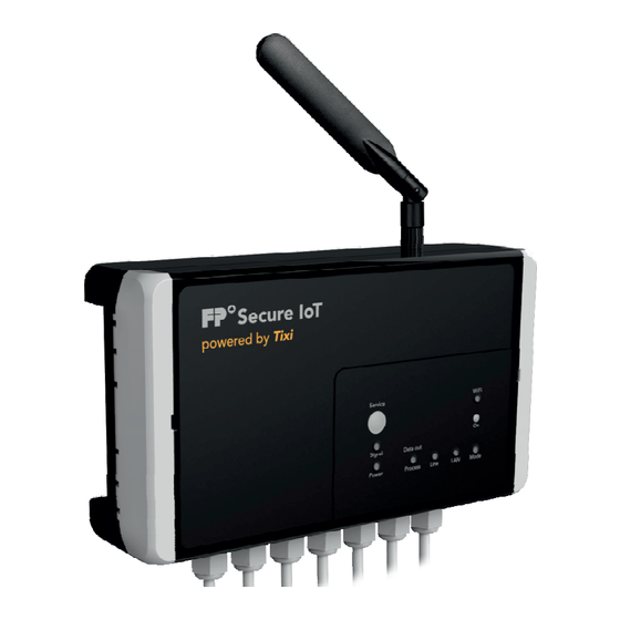
Page 12: Overview Of All Connections
Configuration manual FP S-ENGuard Overview of all connections Model series connection assignments W550 The illustration shows the FP S-ENGuard W550 NB. -
Page 13: Model Series Connection Assignments W640
Overview of all connections Model series connection assignments W640 The illustration shows the FP S-ENGuard W640 BB. -
Page 14: Model Series Connection Assignments W667
Configuration manual FP S-ENGuard Model series connection assignments W667 The illustration shows the FP S-ENGuard W667 BB. -
Page 15: Socket For Backup Battery
3 hours in the event of a power failure. A type with 3.7 V / 750 mA must be used as backup battery. Suitable rechargeable batteries are available from FP InovoLabs GmbH. Fire or damage to property due to incorrect rechargeable batteries Commercially available AA rechargeable batteries (1.2 V) will... -
Page 16: Ethernet Connection
Configuration manual FP S-ENGuard Ethernet connection Key figures at a glance – 10/100 Base-T in accordance with IEC 60028-2-6 – 8P8C port (RJ45), shielded EIA/TIA-568 A/B – Name of connection: LAN Initial start-up and access 5.1.1 IP address of the device The device can be configured via the LAN connection using the parametrisation software TICO or TILA. -
Page 17: Access To The Web Server
U = NB model (NB = narrow band, 2G and/or 3G) T = BB model (BB = broadband/LTE) Example: for FP S-ENGuard W667 BB the Devtype is WT667 Example: Default host name for a model series device W667 BB / WT667... - Page 18 Configuration manual FP S-ENGuard The standard website clearly displays a variety of information on the hardware and configuration of the device. Additionally, the configuration ([System config] button) and the process data ([System properties] button) of the connected sensors (meters, PLCs etc., if configured) can be displayed in...
-
Page 19: Access With The Tila Software
Ethernet connection 5.1.3 Access with the TILA software Start the TILA software. Click the “Online” button on the home page. Double-click on the appropriate entry in the list of possible connections. GPRS/Internet/LAN for connections via the LAN port of the device Tixi WLAN stick for connections via WiFi with the Tixi... -
Page 20: Access With The Tico Software
Configuration manual FP S-ENGuard 5.1.4 Access with the TICO software Start the TICO software. Click on the “Settings” menu item and select “TCP/IP”. Enter the IP address or the host name in the dialogue and click “OK”. -
Page 21: Factory Reset
Ethernet connection Factory reset The device can be reset to factory defaults using the “Service” button. To do so, proceed as follows. Switch off the device. Press the “Service” button (membrane keypad on the upper side) and keep it pressed. Switch on the device. -
Page 22: Integrated Interfaces
Configuration manual FP S-ENGuard Integrated interfaces RS232 Interfaces COM1, COM4 (model dependent) Key figures at a glance – ITU-T V.24, V.28 with handshake – Maximum transmission distance: 12 m – 5 spring terminals each, max 230,400 bps – Signals: RTS, CTS, GND, Rx, Tx –... -
Page 23: M-Bus Interface
– Name of connection terminal: KM1 A fully-fledged M-Bus master is available at connection ter- minal KM1. The configuration of the interface is described in the "FP-SPS-TiXML- Manual". S0 Pulse inputs (Model series W550) Key figures at a glance – 3x pulse inputs according to IEC 62053-31 for passive S0 devices (contacts) –... -
Page 24: Relay Outputs 240 V (Model Series W640, W667)
Configuration manual FP S-ENGuard Relay outputs 240 V (Model series W640, W667) Key figures at a glance – 2x relay changeover contact, 230 V AC 5 A or 110 V DC 0.3 A – Name of connection terminals: Relay 1: KP2, relay 2: KP4 Representation on <Process>... -
Page 25: Digital Inputs 240 V (Model Series W640, W667)
Integrated interfaces Digital inputs 240 V (Model series W640, W667) Key figures at a glance – 2x digital input each 230V AC/3A, Ri = 54 kΩ – Name of connection terminal: KP3 (input 1), KP5 (input 2) Representation on <Process> the process <MB>... -
Page 26: Analogue Inputs (Model Series W667)
Configuration manual FP S-ENGuard Analogue inputs (Model series W667) The model series W667 has permanently installed analogue in- puts at address C092. The A/D converter has a total of 8 channels. The path to the values on the process branch is /Process/092/I_AAAATPPSSB. -
Page 27: Analogue Inputs 0 To 10 V/0 To 20 Ma (P0 To P3)
Integrated interfaces 6.7.1 Analogue inputs 0 to 10 V/0 to 20 mA (P0 to P3) Key figures at a glance – 4x analogue inputs Ω – Voltage input: 0 to 10 V, Ri=100 k Ω – Current input (passive): 0 to 20 mA, Ri=100 –... - Page 28 Configuration manual FP S-ENGuard “Voltage measurement” operating mode Voltage Earth The “Voltage measurement” operating mode can be selected separately for each of the four inputs. In this operating mode, voltages of 0 to 10 V can be measured against earth (factory setting).
- Page 29 Integrated interfaces “Current measurement passive” operating mode Current Earth The “Current measurement passive” operating mode can be se- lected separately for each of the four inputs. In this operating mode, currents from 0 to 20 mA can be measured. Activation of pas- Set both switches of a channel to "P", e.g.
- Page 30 Configuration manual FP S-ENGuard “Current measurement active” operating mode The "Current measurement active" operating mode for current loop sensors (e.g. for pressure, temperature) can be selected separately for each of the four inputs. A current-limited supply voltage of approx. 24 V is provided for each sensor.
- Page 31 Integrated interfaces Example: Input 1 = voltage measurement, scaling from 0 to 10000 Input 2 = current measurement passive, scaling from 0 to 20000 Input 3 = current measurement active, scaling from 0 to 2000 Input 4 = voltage measurement, scaling from 0 to 5000 The A/D converters of the analogue inputs provide raw values between 0 and 3943.
- Page 32 Configuration manual FP S-ENGuard Paths to retrieve the current values from the process branch: – Input 1: /Process/C092/AI_AAAATPPSSB/P0 – Input 2: /Process/C092/AI_AAAATPPSSB/P1 – Input 3: /Process/C092/AI_AAAATPPSSB/P2 – Input 4: /Process/C092/AI_AAAATPPSSB/P3 The values for Tolerance can be specified separately for each channel.
-
Page 33: Pt1000 Inputs (P5, P10, P6, P11)
Integrated interfaces 6.7.2 Pt1000 inputs (P5, P10, P6, P11) Key figures at a glance – 2x Pt1000 inputs – Module address: C092 – Name of connection terminal: M1.X The temperature of both Pt1000 inputs is output once as raw value (P5, P6) and converted to milli degrees Celsius (P10, P11). The measurable temperature range is approx. - Page 34 Configuration manual FP S-ENGuard A sensor is connected to Pt1000 input 1. The raw value (P5) is 1100. The converted value (P10) is 24528 milli degrees Celsius. The Pt1000 input 2 (P6) is open in the example. In this case, the maximum value 4095 and the converted value (P11) 405866 is displayed.
-
Page 35: Analogue Outputs (Model Series W667)
Integrated interfaces Analogue outputs (Model series W667) Key figures at a glance – 3x analogue outputs – Voltage output: 0 to +10 V, Ri=100 kΩ – Current output: 0 to +20 mA, Ri=102 Ω – Resolution: 12 bit (0 to 4095) –... - Page 36 Configuration manual FP S-ENGuard A separate <Module> entry must be defined for each analogue output channel in the peripheral database. The module name is always DAC 1*12Bit. The first output has the address C010 and is displayed in the process branch as follows.
-
Page 37: 1-Wire Bus
Integrated interfaces 1-wire bus Key figures at a glance – Name of connection terminal: KX3/1Wire The 1-wire bus allows the connection of up to 30 sensors, family=10 or family=28. Use externally supplied sensors with 3 connections: GND, VDD, Data. Although parasitically supplied operation is supported in principle, it is not recommended because the bus no longer functions reliably in this operating mode for bus lengths over... - Page 38 Configuration manual FP S-ENGuard Scanning the 1-wire bus To determine which sensors have been detected at the bus the TiXML command ScanDevices can be used. [<ScanDevices _="1Wire" protocol="1Wire"/>]. The command returns all detected sensors in a list view. <ScanDevices> <Device Family="10"...
-
Page 39: System I/Os
Integrated interfaces 6.10 System I/Os Variables path Meaning Remarks /Process/SysIO/P0 Mains power 1: Mains power supply available supply 0: No mains power supply (in battery mode) /Process/SysIO/P1 1-wire overload 1: 1-wire overloading (short circuit, too many sensors) 0: no overloading /Process/SysIO/P2 M-Bus overload 1: M-Bus overloading (short circuit, too many meters) 0: no overloading... -
Page 40: Usb Host Connection
Configuration manual FP S-ENGuard 6.11 USB host connection Key figures at a glance – Name of connections: USB1, USB2 The USB host port can be used to connect USB devices such as memory sticks or WiFi sticks. Via an external USB hub with its own power supply, several devices can also be connected to the device in parallel. -
Page 41: 6.11.2 Using Fp S-Enguard As Wifi Access Point
Integrated interfaces 6.11.2 Using FP S-ENGuard as WiFi access point With a WiFi stick in mini format (available from FP InovoLabs GmbH under order number: 90.0072.8100.00), the device can be operated as an access point and thus the configuration with TILA or TICO can be carried out wirelessly. - Page 42 Configuration manual FP S-ENGuard SSID Name of the access point (ASCII characters, no special characters). Standard: Tixi-Devtype-serial, see chapter 5.1 EnableOnStartup This parameter determines whether the WiFi access point is au- tomatically activated when the system starts. 0=do not activate automatically...
-
Page 43: 6.11.3 Using Fp S-Enguard As Wifi Client
6.11.3 Using FP S-ENGuard as WiFi client With a WiFi stick in mini format (available from FP InovoLabs GmbH under order number: 90.0072.8100.00) the device can be used as a WiFi client. In this mode, the device connects to a WiFi router and can thus be wirelessly integrated into a network. -
Page 44: Supply 24V/50 Ma (Model Series W640, W667)
Configuration manual FP S-ENGuard IP configuration. Currently only the DHCP mode is supported (automatic assignment of IP address, gateway and DNS by the router). Host name Host name by which the device can be reached on the network (if supported by the router). -
Page 45: Debug Port
A serial debug connection (Tx/Rx/GND) is available for devel- opers at the DBG port. The debug port provides a password protected Linux console. Suitable USB adapter cables for connection to a PC are available from FP InovoLabs GmbH. 6.14 Reset button Key figures at a glance –... -
Page 46: Internal Temperature Sensor
Configuration manual FP S-ENGuard 6.16 Internal temperature sensor Key figures at a glance – Name of the sensor: TS An internal temperature sensor is available. Model series W550 The internal temperature sensor is a 1-wire temperature sensor. The temperature sensor must be configured as described in chapter 6.9. -
Page 47: Digital Inputs 24 V (Model Series W550 And W667)
Integrated interfaces 6.17 Digital inputs 24 V (Model series W550 and W667) W550 W550 key figures at a glance – 2x digital inputs – Module address: MB/IO/I – Name of connection terminal: Dig.In W667 W667 key figures at a glance –... -
Page 48: Digital Outputs 48 V/120 Ma (Model Series W550)
Configuration manual FP S-ENGuard 6.18 Digital outputs 48 V/120 mA (Model series W550) Key figures at a glance – 1x digital output via optocoupler, max. 48 V / 120 mA – Module address: MB/IO/Q – Name of connection terminal: Dig.Out The digital output can be wired as follows. -
Page 49: Relay Outputs 30 V/2 A (Model Series W667)
Integrated interfaces 6.19 Relay outputs 30 V/2 A (Model series W667) Key figures at a glance – 3x relay close contacts each 30 V DC / 2 A – Module address: C040 – Name of connection terminal: M5.X Switching of the relay contacts Relay 1 close [<Set _="/Process/C040/Q/P0"... - Page 50 Configuration manual FP S-ENGuard Representation on the process branch <Process> <C040> <Q> <P0 _="0"/> <P1 _="1"/> <P2 _="1"/> </Q> <QB> <P0 _="6"/> </QB> <QW> <P0 _="6"/> </QW> <QD> <P0 _="6"/> </QD> </C040> </Process>...
-
Page 51: Expansion Modules
Expansion modules Expansion modules Depending on the model, the devices of the FP S-ENGuard se- ries have 1 or 5 free sockets for expansion modules. Every socket is addressed via a bus number and a module address. Cbaa = Expansion module... - Page 52 Configuration manual FP S-ENGuard L2 Adapter Two additional sockets (bus numbers 5 and 6) for additional S1 Model series expansion modules are available using the L2 adapter. W667 The screw terminals M6.X and M7.X for connecting sensors are located directly on the L2 adapter.
-
Page 53: S1-Ae3 V1.0 (3 Analogue Inputs, Replaced By S1-Ae3.P V2.0)
Expansion modules S1-AE3 V1.0 (3 analogue inputs, replaced by S1-AE3.P V2.0) Key figures at a glance – 3x analogue inputs; resolution 11bit – Voltage input: 0 to 10V, Ri=100 kΩ – Current input (passive): 0 to 20mA, Ri=120 Ω – Default address for automatic detection: 0x92 Module address Not allowed! (no jumper) - Page 54 Configuration manual FP S-ENGuard [<SetConfig _="PROCCFG" ver="y"> <Periphery> <Module Name="S1-AE3" Address="C694"> <!-- Channel 1 = Analogue Input (1) --> <Numerator0_="10000"/> <Denominator0_="2047"/> <!-- Channel 2 = Analogue Input (2) --> <Numerator1_="10000"/> <Denominator1_="2047"/> <!-- Channel 3 = Analogue Input (3) --> <Numerator2_="10000"/>...
-
Page 55: Conversion Of The Analogue Values To An Input Range Of 4 To 20 Ma
Expansion modules 7.1.1 Conversion of the analogue values to an input range of 4 to 20 mA Many analogue sensors use a range from 4 to 20 mA. The main advantage of these sensors is the easy detection of cable breaks, because in case of a cable break the current is <... - Page 56 Configuration manual FP S-ENGuard Configuration via process variables [<SetConfig _="PROCCFG" ver="y"> <ProcessVars> <!-- the variable pressure outputs the converted value in mbar --> <Pressure type="float" format="F.1" > <Value> <!-- Channel 1 of the onboard module --> <LD _="/Process/C094/AI_PPSSAAA/P0" /> <!-- Restore value to float stack -->...
-
Page 57: S1-S03 (3 Pulse Inputs)
Expansion modules S1-S03 (3 pulse inputs) Key figures at a glance – 3x pulse inputs according to IEC 62053-31 for passive S0 devices (for connecting Reed contacts) – S1-S03: 3x S0 inputs, contact current configurable a)approx. 5 mA, < 5 V at 230 V; maximum cable length: 30 m b)approx. - Page 58 Configuration manual FP S-ENGuard Please note: There are 2 hardware versions V1.0 and V2.0. Module address w/o jumper: Jumper settings for hardware version V2.0 Address PX1 0x3E 0x3C (3-4) 0x3A (1-3) 0xB0 (1-2) 0xB2 (3-4) (1-2) 0xB4 (1-3) (1-2) 0xB6...
- Page 59 Expansion modules Address PX1 0xBC (1-2) (3-4) 0xBE (3-4) (1-2) (3-4) 0xC0 (1-3) (1-2) (3-4) 0xC2 (5-6) 0xC4 (3-4) (5-6) 0xC6 (1-3) (5-6) 0xC8 (1-2) (5-6) 0xCA (3-4) (1-2) (5-6) 0xCC (1-3) (1-2) (5-6) 0xCE (1-2) (5-6) 0xD0 (3-4) (3-4) (5-6) 0xD2 (1-3) (3-4) (5-6)
- Page 60 Configuration manual FP S-ENGuard Database path /PROCCFG/Periphery Syntax [<SetConfig _="PROCCFG" ver="y"> <Periphery> <Module Name="S0 (PIC)" Address="Address"> <Mode _="Mode"/> <SyncPeriod _="SyncPeriod"/> <Numerator1 _="Numerator"/> <Denominator1 _="Denominator"/> <StartValue1 _="StartValue"/> <Numerator2 _="Numerator"/> <Denominator2 _="Denominator"/> <StartValue2 _="StartValue"/> <Numerator3 _="Numerator"/> <Denominator3 _="Denominator"/> <StartValue3 _="StartValue"/> </Module> </Periphery>...
- Page 61 Expansion modules abs Absolute count, synchronised by SyncPeriod. During synchronisation the counted value is copied into a read-only variable and the internal channel counter is not reset. Relative count, synchronised by SyncPeriod. During synchronisation the counted value is copied into a read-only variable and the internal channel counter is reset to 0.
- Page 62 Configuration manual FP S-ENGuard Pulse interface These variables are automatically created by the system and variables displayed in the process branch below the module address of the S0 module. Channel 1 Counted pulses converted with numerator and denomi- nator plus start value.
- Page 63 Expansion modules In the process branch, current values of a S0 module are only displayed if there is a corresponding configuration. In addition to the module identification (Module), a definition of the oper- ating mode (Mode) is mandatory. Default values exist for the remaining configuration entries. SyncPeriod NumeratorX, DenominatorX StartValueX...
- Page 64 Configuration manual FP S-ENGuard Values in the first cycle, after 100 pulses on both interfaces in the process branch. <C03E> <Counter> <P0 _="100" /> <P1 _="400" /> <P2 _="0" /> <P3 _="100" /> <P4 _="100" /> <P5 _="0" /> <P6 _="300" />...
- Page 65 Expansion modules Example 2: S0 plug-in module with 3 channels in socket 5 has module address 0x3C (Bus 6). Channel 1 = Synchronous channel for channel 2 Channel 3 = absolute counting No scaling used. Syncronisation every 15 minutes (900 s; only applies to channel 3 because channel 2 is synchronised by channel 1), start value for channel 3 = 1400.
- Page 66 Configuration manual FP S-ENGuard Values for the second cycle after 50 pulses on channel 2 and 3. For simplification, it is assumed that the synchronous pulse for channel 1 occurs simultaneously with the in- ternal synchronous event after 900 seconds.
-
Page 67: S1-Dxx (Digital Inputs And Outputs)
Expansion modules S1-Dxx (Digital inputs and outputs) Module address Module type Pin assignment on screw terminal S1-D50 S1-D30G -IN1 +IN1 -IN2 +IN2 -IN3 +IN3 S1-D05 OUT0 OUT1 OUT2 OUT3 OUT4 S1-D03G OUT0 OUT1 OUT2 Standard module address: x40 (all jumpers set to 0) Please always set all jumpers (0 or 1). -
Page 68: S1-D50 (5 Digital Inputs)
Configuration manual FP S-ENGuard 7.3.1 S1-D50 (5 digital inputs) Key figures at a glance – 5x digital inputs (for potential-free contacts/relays or digital signals) – Low: 0 to 1 V, High: 3.5 V .. 24 V – Internal pull-up approx. 2 kΩ... - Page 69 Expansion modules Representation of the inputs on the process branch Example: Module S1-D50, module address 0x40, socket 2 (bus 3) <Process> <C340> <I> <P0 _="1"/> <P1 _="1"/> <P2 _="1"/> <P3 _="1"/> <P4 _="1"/> </I> <IB> <P0 _="31"/> </IB> <IW> <P0 _="31"/> </IW>...
-
Page 70: S1-D05 (5 Digital Outputs)
Configuration manual FP S-ENGuard 7.3.2 S1-D05 (5 digital outputs) Key figures at a glance – 5x digital outputs; optocoupler with common earth (earth is connected to device earth) – Dielectric strength: 48 V – max. current: 120 mA; OnResistance: approx. 25 Ω... - Page 71 Expansion modules Representation of the outputs on the process branch Example: Module S1-D05, module address 0x40, socket 1 (bus 2) <Process> <C240> <Q> <P0 _="1"/> <P1 _="0"/> <P2 _="1"/> <P3 _="1"/> <P4 _="0"/> </Q> <QB> <P0 _="31"/> </QB> <QW> <P0 _="31"/> </QW>...
-
Page 72: S1-D03G (3 Digital Outputs, Galvanically Isolated)
Configuration manual FP S-ENGuard 7.3.3 S1-D03G (3 digital outputs, galvanically isolated) Key figures at a glance – 3× independent digital outputs; electrically isolated via optocoupler – Dielectric strength: 48 V – max. current: 100 mA; OnResistance: approx. 25 Ω – Default module address: 0x40... - Page 73 Expansion modules Representation of the outputs on the process branch Example: Module S1-D03G, module address 0x42, socket 4 (bus 5) <Process> <C542> <Q> <P0 _="0"/> <P1 _="0"/> <P2 _="0"/> </Q> <QB> <P0 _="0"/> </QB> <QW> <P0 _="0"/> </QW> <QD> <P0 _="0"/> </QD>...
-
Page 74: S1-Pt3 (3 Pt1000 Inputs)
Configuration manual FP S-ENGuard S1-PT3 (3 Pt1000 inputs) Key figures at a glance – 3x Pt1000 inputs – Default module address: 0x96 Module Address (no jumper) The conversion from voltage U [mV] to degrees Celsius is auto- matic. The raw value of the A/D converter is not displayed. - Page 75 Expansion modules Representation of the outputs on the process branch Example: Module S1-PT3, module address 0x96, socket 4 (bus 5) <Process> <C596> <I> <P0 _="0"/> <P1 _="22410"/> <P2 _="0"/> </I> </C596> </Process> In the example above, the value 22410 milli degrees Celsius = 22.41 °C is displayed for the Pt1000 temperature sensor at input 2, the other PT1000 temperature sensors show the value If no Pt1000 temperature sensor is connected, a value of ap-...
-
Page 76: S1-Wl2 (2 Relay Outputs, Changeover Contact)
Configuration manual FP S-ENGuard S1-WL2 (2 relay outputs, changeover contact) Key figures at a glance – 2x relay outputs (changeover contacts) – Maximum 48 V/3 A – Default module address: 0x42 Module Address... - Page 77 Expansion modules Representation of the outputs on the process branch Example: Module S1-WL2, module address 0x42, socket 5 (bus 6) <Process> <C642> <Q> <P0 _="0"/> <P1 _="1"/> </Q> </C642> </Process> In the example, the normally open contact of relay 1 is open (NO1) and the normally open contact of relay 2 is closed (NO2).
-
Page 78: S1-Aa2 (2 Analogue Outputs)
Configuration manual FP S-ENGuard S1-AA2 (2 analogue outputs) Key figures at a glance – 2x analogue outputs; resolution 12bit – Voltage output: 0 to 10 V, Ri=100 kΩ – Current output: 0 to 20 mA, Ri=120 Ω – Default address for automatic detection:... - Page 79 Expansion modules Representation of the outputs on the process branch Example: Module S1-AA2, address 0x10/0x12, socket 5 (bus 6) Output 1 <C610> <AO> <P0 _="1000"/> </AO> </C610> Output 2 <C612> <AO> <P0 _="1000"/> </AO> </C612>...
- Page 80 Configuration manual FP S-ENGuard The analogue outputs can be scaled via the peripheral data- base. Example: Module S1-AA2, address 0x18 (channel 1), socket 5 (bus 6) Scaling to 0 to 2000, maximum raw value of the D/A converter: 4027 [<SetConfig _="PROCCFG" ver="y">...
-
Page 81: S1-Ae3.0 V2.0 (3 Analogue Inputs, Replaced By S1-Ae3.P V2.0)
Expansion modules S1-AE3.0 V2.0 (3 analogue inputs, replaced by S1-AE3.P V2.0) Key figures at a glance – 3x analogue inputs; resolution 11bit – Voltage input: 0 to 10 V, Ri=100 kΩ – Current input (passive): 0 to 20 mA, Ri=120 Ω –... - Page 82 Configuration manual FP S-ENGuard The analogue inputs can be switched between 0 to 10 V and 0 to 20 mA via jumpers. The factory setting is 0 to 10 V. The A/D converters of the analogue inputs provide raw values between 0 and 2029.
- Page 83 Expansion modules Representation of the inputs on the process branch Example: Module S1-AE3.0, voltage measurement, address 0x92, Scaling 0 to 10000 mV, socket 4 (bus 5) <Process> <C592> <AI_AAA> <P0 _="5000"/> <P1 _="2500"/> <P2 _="0"/> </AI_AAA> </C592> </Process> Material damage due to incorrect installation of the modules Incorrect installation of the modules may result in material damage to the expansion modules.
-
Page 84: S1-Ae3.P V2.0 (3 Analogue Inputs)
Configuration manual FP S-ENGuard S1-AE3.P V2.0 (3 analogue inputs) Key figures at a glance – 3x analogue inputs; resolution 11bit – Voltage input: 0 to 10 V, Ri=100 kΩ – Current input: 0 to 20 mA, Ri=120 Ω – Current input (active): 0 to 20 mA –... - Page 85 Expansion modules In the "voltage = U" and "current = I passive" (factory setting) operating mode the lower jumpers per channel must be set to "A" (2 jumpers per channel). In "current = I passive" mode the module behaves like a S1-AE3 in "I” mode. In the "voltage = U"...
- Page 86 Configuration manual FP S-ENGuard Representation of the inputs on the process branch Example: Voltage measurement, address 0x92, scaling 0 to 10000 mV, socket 4 (bus 5) <Process> <C592> <AI_AAA> <P0 _="5000"/> <P1 _="2500"/> <P2 _="0"/> </AI_AAA> </C592> </Process> Measurement: Input 1 = 5000 mV...
- Page 87 Expansion modules Details on the operating modes Voltage Voltage measurement measurement Voltage Earth When measuring voltage, voltages of 0 to 10 V can be meas- ured against earth (factory setting). The left screw terminal of a channel (K1.1, K2.1, K3.1) is the earth connection, the right screw terminal (K1.2, K2.2, K3.2) is the voltage input.
- Page 88 Configuration manual FP S-ENGuard In the "Current measurement passive" mode, current from 0 to 20 mA is measured against earth. The left screw terminal of a channel (K1.1, K2.1, K3.1) is the earth connection, the right screw terminal (K1.2, K2.2, K3.2) is the cur- rent input.
-
Page 89: Restrictions For The Operation Of Passive Sensors
Due to the limitation of the power supply units used, the fol- lowing restrictions apply to the operation of passive sensors on S1-AE203 and S1-AE3.P depending on the model. FP S-ENGuard If the 24V terminal (KP24) is loaded and the integrated ana- Model series logue outputs are not operated as current outputs, max. -
Page 90: S1-D30G (3 Digital Inputs, Galvanically Isolated)
Configuration manual FP S-ENGuard S1-D30G (3 digital inputs, galvanically isolated) Key figures at a glance – 3x digital inputs, galvanically isolated – Low: 0 to +9.2 V, High: +10.4 V to +60 V – Maximum input voltage: -60 V to +60 V –... - Page 91 Expansion modules Display of the logical levels In contrast to the other digital input modules, an open input in the process branch of the S1-D30G is indicated as "0". When the high level is reached, the display changes to "1". Representation of the inputs on the process branch Example: Module S1-D50, module address 0x40, socket 2 (bus 3) <Process>...
- Page 92 Configuration manual FP S-ENGuard...
-
Page 93: Index
L2 Adapter (W667 only) 52 COM2 22 COM4 22 COM5 22 Configuration Factory reset 21 Prerequisites 6 FP InovoLabs GmbH 2 Connection assignments available-to-order accessories 15, 41, 43, W550 12 W640 13 Download of documents 6 W667 14 Contact Information 2... - Page 94 Configuration manual FP S-ENGuard S1-D30G 90 Display of the logical levels 91 Material numbers of the models 10 S1-D50 68 M-Bus 23 S1-Dxx 67 Memory stick. See USB memory stick S1-PT3 74 Models and equipment 10 S1-S03 57 S1-WL2 76...
- Page 95 Index Web server 17 WiFi access point Using FP S-ENGuard 41 WiFi client 43 Using FP S-ENGuard 43 WiFi stick 41 order 41 1-wire bus 37 scanning 38 WPS 42 Turning on WPS mode 42...
- Page 96 Notes...
- Page 97 Notes...
Need help?
Do you have a question about the S-ENGuard W550 Series and is the answer not in the manual?
Questions and answers