Table of Contents
Advertisement
Advertisement
Table of Contents

Related Manuals for Muller Elektronik SMART570


Summary of Contents for Muller Elektronik SMART570
- Page 1 Installation and operating instructions SMART570 Version: V7.20210115 30322507-02-EN Read and follow these instructions. Keep these instructions in a safe place for later reference. Please note that there might be a more recent version of these instructions on the homepage.
- Page 2 Company details Document Installation and operating instructions Product: SMART570 Document number: 30322507-02-EN As of software version: 0.3.2.0 Original instructions Original language: German Copyright © Müller-Elektronik GmbH Franz-Kleine-Straße 18 33154 Salzkotten Germany Phone: ++49 (0) 5258 / 9834 - 0 Fax: ++49 (0) 5258 / 9834 - 90 Email: info@mueller-elektronik.de...
-
Page 3: Table Of Contents
Table of contents Table of contents For your safety Basic safety instructions Intended use Layout and meaning of warnings About these Operating Instructions Target group of these Operating Instructions Directional information in these instructions Layout of operating instructions Layout of references Product description Scope of delivery Front... - Page 4 Table of contents Diagnostics 6.5.1 Diagnostic of connected devices 6.5.2 Deleting the object pool Information Technical specifications Technical specifications of the terminal Pin assignment 7.2.1 9-pin CPC connector 7.2.2 5-pin M12 connector Appendix Updating the terminal V7.20210115 30322507-02-EN...
-
Page 5: For Your Safety
For your safety Basic safety instructions For your safety Basic safety instructions Please read the following safety instructions carefully before using the product for the first time. ▪ Before maintenance or repair to the tractor, always disconnect the connection between the tractor and the terminal. - Page 6 For your safety Layout and meaning of warnings NOTICE This signal word identifies hazards that could potentially cause damage to property, if not avoided. There are some actions that need to be performed in several steps. If there is a risk involved in carrying out any of these steps, a safety warning appears in the instructions themselves.
-
Page 7: About These Operating Instructions
About these Operating Instructions Target group of these Operating Instructions About these Operating Instructions Target group of these Operating Instructions These Operating Instructions are intended for personnel entrusted with installing and operating the terminal. Directional information in these instructions All directional information in these instructions, such as “left”, “right”, “forward”, “back”, is relative to the movement direction of the vehicle. -
Page 8: Product Description
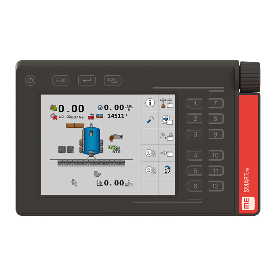
Universal Terminal (UT) on all ISOBUS machines, regardless of manufacturer. The integrated ISOBUS functions are AEF certified. The colour display of the SMART570 has a resolution of 640 x 480 pixels. The SMART570 offers a capacitive touch screen, a membrane keyboard and a rotary encoder for optimum operation of the connected implement. -
Page 9: Rear
Product description Rear Buttons on the casing Function icons Depiction of an available function. The functions are executed when you press on the respective function button. Rotary encoder Screen content Rear Rear view Thread for the bracket screws Speaker Connection to the 7-pin signal socket Connection to ISOBUS Pressure compensation membrane (must never be covered) -
Page 10: Eu Declaration Of Conformity
Product description EU declaration of conformity Information on the rating plate Entry Meaning SMART570 Name of the product Made in Germany Country of manufacture Year of Mfg. Year of manufacturing Input Operating voltage 9-16 V, ⎓ = DC voltage, current consumption... -
Page 11: Installation
Installation Mounting the terminal in the vehicle cab Installation Mounting the terminal in the vehicle cab Procedure 1. Screw the terminal plate onto the rear of the terminal: Always use all four screws supplied. 2. Unscrew the long bolt out of the pipe bracket: 3. -
Page 12: Connecting Sensors To The Terminal
Installation Connecting sensors to the terminal ⇨ You have connected the terminal to the ISOBUS. Connecting sensors to the terminal The terminal can receive signals from the following sensors: ▪ Work position sensor Purpose: – Display of the work position on the start screen. –... -
Page 13: Basic Control Principles
Basic control principles Initial start-up Basic control principles Initial start-up For the initial start-up, you must switch on and configure the terminal. Procedure The terminal is installed and connected to the ISOBUS. - Start the terminal. ⇨ The terminal will now be started. ⇨... -
Page 14: Operating The Terminal Using The Screen
Basic control principles Operating the terminal Illustration Action Function Pushing the rotary Clicks on the marked line. encoder Activates the marked parameter. Confirms the input. Buttons The following functions can be executed with the buttons on the casing: Button Designation Function ON/OFF button Pressing the button for 1 second: Switches the terminal... -
Page 15: Changing Parameters
Basic control principles Changing parameters Changing parameters 5.3.1 Changing parameters using the screen Procedure 1. Call up a screen with adjustable parameters. For example: 2. Press on the parameter that you want to change. 3. Change the value. - Confirm the input. 5.3.2 Changing parameters with the rotary encoder Procedure... -
Page 16: Using The Joystick
Basic control principles Using the joystick Using the joystick If an AUX-2 operating device (e.g.: joystick) is detected, an overview of the configured button assignment is shown every time the terminal is started. Procedure You have started the terminal. 1. -
Page 17: Configuration Of The Terminal
Configuration of the terminal App selection Configuration of the terminal From the start screen of the terminal, you can configure different terminal parameters and functions. The individual parameters can be configured at several points. If parameters are greyed out, they cannot be changed. They only serve as information. Procedure - Start the terminal. -
Page 18: System Settings
Configuration of the terminal System settings System settings You can change the different basic system settings on this screen. Path On the start screen, press: Controls The following function icons appear on the screen: Function icon Meaning Switches back to the previous screen. Changes the brightness mode. -
Page 19: Formats And Units
Configuration of the terminal System settings Parameter Meaning When this parameter is activated, the connected job computer switches to safe mode when the ON/OFF button ( ) is briefly pressed. Moreover, an alarm message appears. Volume Volume of the terminal. Keyboard brightness Activation/deactivation of the keyboard illumination. -
Page 20: Terminal
Configuration of the terminal System settings 6.3.2 Terminal On this screen, you can define how the terminal should identify itself and react on the bus. Path On the start screen, press: > Controls The following function icons appear on the screen: Function icon Meaning Switches back to the previous screen. -
Page 21: Calibrating The Speed Sensor
Configuration of the terminal System settings Function icon Meaning Calls up the screen for calibrating the speed sensor. Calls up the screen with the counters. Parameter The following parameters can be configured on this screen: Parameter Meaning Speed signal Source for the speed signal. Sensor - A speed sensor is connected to the terminal. -
Page 22: Counters
Configuration of the terminal System settings ⇨ The following screen appears: - Open the calibration screen. ⇨ The following screen appears: - Start the calibration. 6. Drive straight ahead over the marked distance. 7. Stop after 100 m. - Terminate the calibration. ⇨... -
Page 23: Button Assignment For Aux Operating Devices
Configuration of the terminal Button assignment for AUX operating devices Function icon Meaning Switches back to the previous screen. Resets all counters, except for the operation hours, back to 0. Parameter The following parameters can be configured on this screen: Parameter Meaning Applied area in ha... -
Page 24: Diagnostics
Configuration of the terminal Diagnostics Procedure The joystick and ISOBUS job computer are connected. 1. On the start screen, press: - Select whether you want to make the assignments directly by pressing the buttons on the joystick or through the terminal. ⇨... -
Page 25: Diagnostic Of Connected Devices
Configuration of the terminal Diagnostics Function icon Meaning Switches to the screen for deleting object pools. Parameter The following parameters can be configured on this screen: Parameter Meaning Supply voltage Current supply voltage. Operating Current processor temperature. temperature Available/used Currently free and used memory. memory If there is no more available memory, you must delete one or more object pools. -
Page 26: Deleting The Object Pool
Configuration of the terminal Diagnostics Symbol for the respective device type ISO name Manufacturer CAN bus address 6.5.2 Deleting the object pool Each job computer that is connected to the ISOBUS copies the images, texts and other objects used in its software onto the terminal. These files are collectively referred to as object pool. Since the memory on the terminal is limited, it is sensible to delete the object pools for job computers that are not in use. -
Page 27: Information
Configuration of the terminal Information Information On this screen, you are given information regarding the terminal. Path On the start screen, press: Controls The following function icons appear on the screen: Function icon Meaning Switches back to the previous screen. Parameter The following parameters can be configured on this screen: Parameter... -
Page 28: Technical Specifications
Technical specifications Technical specifications of the terminal Technical specifications Technical specifications of the terminal Operating voltage 9 – 16 V, ⎓ Ambient temperature -20 – +55 °C Storage temperature -30 – +85 °C Weight Approx. 850 g without bracket Dimensions (W x H x D) 212 mm x 135 mm x 44 mm Ingress protection code IP6K6 in accordance with ISO 20653... -
Page 29: Pin Assignment
Technical specifications Pin assignment Pin assignment 7.2.1 9-pin CPC connector Signal Meaning ECU_PWR Supply +12 V CAN_L_In CAN Input CAN_L_Out CAN Output CAN_H_In CAN Input CAN_H_Out CAN Output TBC_PWR Ignition Input ECU_PWR Supply +12 V Not connected ECU_GND Ground 7.2.2 5-pin M12 connector Signal Meaning... -
Page 30: Appendix
Appendix Updating the terminal Appendix Updating the terminal Procedure When you want to update the software on the terminal, proceed as follows: You have a new software version for installation. You have the Downloadmanager 2 software on your PC and you have connected the PC to the terminal.
Need help?
Do you have a question about the SMART570 and is the answer not in the manual?
Questions and answers