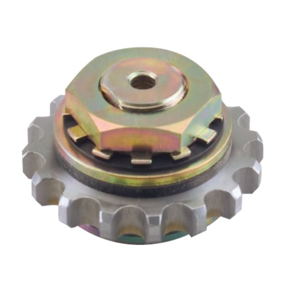
Summary of Contents for Tsubaki TORQUE LIMITER Series
- Page 1 DATE 2020/09/09 Bulletin No.05A01TS00E INSTALLATION MANUAL TORQUE LIMITER Series TL10(C)~TL20(C) 1/10...
- Page 2 Safety Guide and Warranty Death or serious injury may result from product misuse due to not WARNING following the instructions. “Mechanical type Safety and Control devices” ⚫ Begin inspection and maintenance after verifying that no load or rotational force is being applied to the equipment.
- Page 3 Minor or moderate injury, as well as damage to the product may CAUTION result from product misuse due to not following the instructions. “Mechanical type Safety and Control devices” ⚫ The strength of the equipment should be designed to withstand the load or rotational force when the device is activated due to overload.
- Page 4 Thank you for purchasing a Torque Limiter. Make sure the unit delivered matches your order and no shortages exist in the parts provided. Any such shortages or other delivery errors must immediately be reported to your distributor. This manual should be considered an essential part of the Torque Limiter and remain with the coupling when redistributed.
-
Page 5: Torque Setting
2. Machining accuracy on center member ① Finish the friction face sides of the center member(both sides)in 3s-6s. ② In addition machine the bore diameter of the center member in accordance with the dimensional tolerance in the catalog. 3. Run-in Usually, run-in operations for the Torque Limiter are not necessary. - Page 6 6/10...
- Page 7 5. Tightening method for adjustable bolts Make sure Spirolox is surely in the ditch. The Pilot plate for TL10 have 8 pcs. of adjustable bolts, for TL14 and TL20 have 5 pcs. adjustable bolts. Place the Spring plate and Disc spring in contact with each other, and tighten the Adjustable bolts manually until there is no backlash between their faces.
- Page 8 9. Installing the Torque Limiter Coupling Align the shaft centers by calibrating the angular and parallel misalignments. Measure by placing the scale by the sprocket teeth. Adjust the length between the sprockets or dimension S, and their parallelism according to the dimensions provided below. Then wrap the chain around the sprockets and lock with a joint pin.
-
Page 9: Warranty
TSUBAKIMOTO CHAIN CO.: hereinafter referred to as “Seller” Warranty: Customer: hereinafter referred to as “Buyer” Goods sold or supplied by Seller to Buyer: hereinafter referred to as “Goods” 1. Warranty period without charge Effective 18 months from the date of shipment or 12 months from the first use of Goods, including the installation of the Goods to the Buyer’s equipment or machine - whichever comes first. - Page 10 1-1, Kohtari-Kuresumi, Nagaokakyo TSUBAKIMOTO CHAIN CO. Kyoto 617- 0833, Japan Website: http://tsubakimoto.com/ Global Associated Partners: U.S. Tsubaki Power Transmission, LLC Tsubakimoto Singapore Pte. Ltd. Tsubakimoto Europe B.V. http://www.ustsubaki.com/ http://tsubaki.sg/ http://tsubaki.eu/ Tsubaki of Canada Limited Taiwan Tsubakimoto Co.


Need help?
Do you have a question about the TORQUE LIMITER Series and is the answer not in the manual?
Questions and answers