
Summary of Contents for Southwest Microwave INTREPID MicroTrack II
- Page 1 Southwest Microwave, Inc. Security Systems Division INTREPID™ MicroTrack ™ II A BURIED TERRAIN-FOLLOWING OUTDOOR PERIMETER INTRUSION DETECTION SYSTEM MicroTrack II Installation and Operation Manual Version 0...
- Page 2 ...
- Page 3 INTREPID MicroTrack II Manual INTREPID™ MicroTrack™ II Software Southwest Microwave Inc. thanks you for your purchase of the INTREPID MicroTrack II System. Please refer to the Universal Installation Service Tool (UIST) for the software setup of this sensor. There is one disk required to setup the system 1.
- Page 4 ...
- Page 5 This equipment has been designed and tested to meet EN 6950-1, EN 300-330-1, EN 300-330-1-7.2, EN 300-330-1-7.4.2 and EN 300-330-1-8.2. Patent Notice Southwest Microwave Inc. intellectual property in INTREPID and MicroTrack is protected by the following patents: 6,577,236,B2 Patents are pending in many counties of the world.
- Page 6 ...
-
Page 7: Table Of Contents
INTREPID MicroTrack II Manual TABLE OF CONTENTS Introduction ............................... 1-1 Theory of Operation ..........................1-1 Target Processing ..........................1-3 Features and Benefits .......................... 1-5 MicroTrack™ II Detection Characteristics .................... 2-1 Detection Requirements and Expectations ..................2-1 MicroTrack II Typical Detection Pattern .................... 2-1 2.2.1... - Page 8 INTREPID MicroTrack II Manual Installation of the Sensor Cable ....................... 6-1 Burying Sensor Cables in Soil ......................6-1 Burying Sensor Cables in Concrete/Asphalt, Thickness of 4 in. (10cm) or more ....... 6-3 Burying Sensor Cables in Concrete/Asphalt, Thickness of 4 in. (10cm) or less … ......6-3 Burying Sensor Cables in Different Mediums ..................
-
Page 9: Introduction
INTREPID MicroTrack II Manual Introduction Welcome to Southwest Microwave Inc.’s new buried cable outdoor perimeter intrusion detection system – MicroTrack™ II – the most advanced buried cable sensor system available. MicroTrack II is the first buried cable sensor that is truly site-adaptive and can both detect and locate intruders. It is patented and it is the first outdoor intrusion detection sensor to use ultra wide band FS/PCM (frequency stepped, phase code modulated) technology. - Page 10 INTREPID MicroTrack II Manual 200m Max. Transmiter Termination Analog Convert Receiver System Gain Set 0-255 Clutter + Target System Process Cable Clutter Tamper Clutter Fault Location Location Detection Display Cable Fault Clutter Alarm Remove Stored Calib. Input Clutter Calib. Display...
-
Page 11: Target Processing
INTREPID MicroTrack II Manual The volumetric detection field is comprised of two components, defined here as clutter and target. Clutter is the static field that is developed between the cables without a target present as shown in Figure 1.4. The target component is the change in the static clutter as an intruder enters the volumetric field. - Page 12 INTREPID MicroTrack II Manual Figure 1.5 - Intruder Entering the Volumetric Detection Field The next step is to process the Target Input values into location data. Again the Fast Fourier Transform is employed to perform this function. With no target present the resulting output is the noise level of the system as a function of range.
-
Page 13: Features And Benefits
Figure 1.7 is an example of an intruder entering the detection field. Figure 1.7 - Intruder entering the Detection Field The alarm information is available by polling the MicroTrack™ II sensor. The Southwest Microwave MicroTrack II SDK -Polling Protocol Specification allows alarm, fault & tamper status to be easily accessed over RS422 data lines or direct connection by RS232 to the processor. - Page 14 ...
-
Page 15: Microtrack™ Ii Detection Characteristics
INTREPID MicroTrack II Manual MicroTrack™ II - Detection Characteristics The MicroTrack II Sensor consists of the MicroTrack Processor II (MTP II) and either one or two sets of buried sensor cables (MTC400) with MicroTrack End of Line Termination (MTT) units or MicroTrack In Line Termination (MTI) units on the ends of each cable assembly. - Page 16 INTREPID MicroTrack II Manual This is because a small target close to the cables will appear to be the same “size” as a larger target further away from the cables. Figure 2.1 - MicroTrack can Detect Large Targets in Secondary Field It is important to recognize the existence of this secondary field because it governs the safe distance from which MicroTrack™...
-
Page 17: Detection Pattern Width
INTREPID MicroTrack II Manual When two cable sets from the same MTP II or adjacent MTP II’s meet at a common point, they will be connected and terminated with two MTI In Line Termination units to allow the Detection Fields to slightly overlap, forming a continuous detection zone. -
Page 18: Sensor Cable Maximum Length
INTREPID MicroTrack II Manual Figure 2.3 –Typical Detection Fields Cross Sectional Shape for 5 Foot (1.5m) Spacing The cable burial depth and the burial mediums conductivity do not have a significant affect on the detection patterns height. As a rule of thumb, with the MTP II at default settings (Threshold = -12 dB) and the cables spaced 5 feet (1.5 meters) apart, the detection field for a slow walking person crossing on a wooded plank is... - Page 19 INTREPID MicroTrack II Manual The next important factor is the MTP II’s Threshold setting. The default setting is –12 dB and is the nominal setting for most applications. At this or any setting, the concern is with the difference between the calibration profile and the noise level.
- Page 20 ...
-
Page 21: Microtrack Ii System Components
INTREPID MicroTrack II Manual MicroTrack™ II System Components MicroTrack II system components are presented in three categories: hardware, controllers and software components. 3.1 Hardware Components 3.1.1 MicroTrack Processor II (MTP II) The MTP II is the principal component of the MicroTrack II system. It provides all the electronic processing for two-210 m (689 ft.) sensor cable sets for a total perimeter length of 400 m (1312 ft.). -
Page 22: Microtrack Sensor Cable Assembly
INTREPID MicroTrack II Manual 3.1.2 MicroTrack™ Sensor Cable Assembly (MTC400-110, MTC400-210) An MTC400-110 or MTC400-210 sensor cable assembly consists of one spool of sensor cable with 66 feet (20 meters) of lead-in cable attached. Cable junctions are factory made to ensure high integrity. A TNC connector is installed on the lead-in cable to connect with the MTP. -
Page 23: Microtrack In Line Termination Kit (Mti)
INTREPID MicroTrack II Manual 3.1.4 MicroTrack™ In Line Termination Kit (MTI) MTI’s are an in-line termination used to terminate the detection field at the end of a Sensor Cable Assembly that is overlapping another Sensor Cable Assembly. The MTI kit includes an enclosure with adapters, strain reliefs, two 51 ohm resistors, vinyl boot and potting compound. -
Page 24: Microtrack Splice Kit (Mts)
INTREPID MicroTrack II Manual 3.1.7 MicroTrack™ Splice Kit (MTS) A splice kit is used to repair a damaged section of sensor cable. A kit includes two splice boxes, a large and small splice connector, heat shrink and potting compound. A length of MTC400 sensor cable is required and must be ordered separately by the foot or meter. -
Page 25: Power Supplies
INTREPID MicroTrack II Manual 3.1.11 Power Supplies 12 VDC power supply: Model PS13 Power Supply operates from 85-246VAC, 47-63Hz and furnishes 13.6 VDC at up to 2.8A. Power supplies contain automatic switchover and battery charging circuitry for optional standby batteries of up to 25AH. Temperature rated from 14° to 122° F (-10° to 50° C). UL, ETS, EMC, CE, RoHs compliant. -
Page 26: Perimeter Security Manager
INTREPID MicroTrack II Manual 3.2.4 Perimeter Security Manager (PSM) Software Perimeter Security Manager is a software package that provides easy-to-use operator command and control for MicroTrack™, MicroPoint™, MicroTrack II, MicroPoint II, 330 MicroWave, AIM II, ROM II and auxiliary sensors. It uses Microsoft Windows™ based software (2000 Pro, XP Pro or Windows 7) and a PC with a color monitor to display all sensor zones on a custom site map. -
Page 27: Site Planning / System Configuration
INTREPID MicroTrack II Manual Site Planning / System Configuration This chapter describes several MicroTrack™ II Processor typical configurations. Other INTREPID™ devices used in these configurations will also be shown. 4.1 Basic MicroTrack II Configuration Parameters MicroTrack II can be configured in many ways and used in conjunction with a wide variety of complementary devices. - Page 28 INTREPID MicroTrack II Manual There is one (1) Relay Control Module II (RCM II) attached that will be the controller (poll master) to monitor alarms from the MTP II and provide relay outputs and two (2) Relay Output Module II (ROM II) devices for relay outputs to annunciating equipment.
- Page 29 INTREPID MicroTrack II Manual Figure 4.2 shows a minimum system configuration. The very minimum requirements will be one (1) MTP II, 1 Sensor Cable set, 2 MTT’s, 1 Power Supply, 2 JB70A Surge Module and one (1) RCM II. A PC running an alarm monitoring program such as the Perimeter Security Manager or the GCM II can be substituted for the RCM II for graphic alarm annunciation.
- Page 30 INTREPID MicroTrack II Manual wiring has been purposely omitted as it is shown in each device’s manual and in a later chapter. The A cables are overlapped with B cables and TX cables and RX cables are in the same trenches.
-
Page 31: Site Survey
INTREPID MicroTrack II Manual Figure 4.3 also shows that the power and data wiring can be in the same conduit for a direct connection to the first MTP II. An alternative to the independent conduit wire runs is to include the power and data wiring in the same trench as the sensor cables. - Page 32 ...
-
Page 33: System Design
INTREPID MicroTrack II Manual System Design This section will provide guidance on how to design a MicroTrack™ II System. It includes information on sensor performance characteristics, selecting cable spacing, burial depth, and maximum sensor cable lengths, how the sensor cables should be installed in different burial mediums, how to deal with various site environmental conditions, and how to layout the sensor cables. -
Page 34: Animals And The Detection Field
INTREPID MicroTrack II Manual Primary Detection Field Secondary Detection Field Roads and vehicles 6.6 ft (2m) 3.3 to 6.6 ft (1 to 2m) 8 to 20 ft (2.4 to 6.1m) 20 ft (6.1m) Figure 5.1 - MicroTrack II Detection Field Proximity to Fences & Roads for Typical Site Conditions 5.3 Animals and the Detection Field... -
Page 35: Uneven Terrain
INTREPID MicroTrack II Manual MicroTrack™ II can also be installed close to and around trees, large or small as shown in Figure 5.2. A concern with installing sensor cables close to trees is the potential damage to the tree(s) root system resulting from trenching. -
Page 36: Rain, Standing Water And Run-Off
INTREPID MicroTrack II Manual Figure 5.3 - MicroTrack™ II Detection Field is Terrain Following 5.6 Rain, Standing Water and Run-off Rain typically falling through the detection field will not affect detection performance nor cause nuisance alarms. The issue to be concerned with is the water after it reaches the ground. If water is allowed to run across or accumulate into large puddles of approximately 3.3 to 6.6 feet (1 to 2 m) over the sensor cables,... -
Page 37: Positioning Microtrack Ii Components On The Perimeter
INTREPID MicroTrack II Manual Figure 5.4 - Encouraging water runoff reduces potential nuisance alarms from moving water It is important to note that standing water is not a problem for MicroTrack™ II, and neither is having the sensor cables installed in a totally saturated burial medium, e.g., mud. The problem is moving water near... - Page 38 INTREPID MicroTrack II Manual 4. Allow for the 16 feet (5 m) startup on each side of the MTP II. 5. Locate the MTP II centrally between the two sensor cable sets. 6. Determine if an auxiliary sensor will be required to close gaps at buildings, and if so, include an Alarm Input Module II (AIM II) and provide data communications and power.
-
Page 39: Selecting The Optimum Sensor Cable Spacing
INTREPID MicroTrack II Manual • Inner sensor cable. Stake the location of the inner sensor cable based on the sensor cable spacing selected. Stake the start points at each MTP II, corner points and the end points, as above. •... - Page 40 INTREPID MicroTrack II Manual Figure 5.6 - MicroTrack II Primary Detection Field and Cable Spacing The formula for calculating the cable spacing relative to fences and buildings is a 3 to 1 ratio as shown in Figure 5.7. Using this figure as the example, if the cable spacing “Y” is 5 feet (1.5m) then from centerline of the MicroTrack cables to the fences, “3 x Y”, would be 15 feet (4.6m).
-
Page 41: Double Fences, Concertina And Razor Tape
INTREPID MicroTrack II Manual In general, the cable spacing is the primary control for the detection width. The MTP II’s Sensitivity settings will have a smaller affect on the width of the detection field. Typical detection patterns are illustrated in Figure 2.3. -
Page 42: Cable Spacing Near Buildings
INTREPID MicroTrack II Manual Many high security sites use barbed concertina wire or razor tape on fence tops, as well as stacked on the ground, as illustrated in Figure 5.8. Concertina and razor tape can cause electrical noise as a result of wind action or thermal changes resulting in nuisance alarms if placed too close to MicroTrack™... -
Page 43: Installation Of The Sensor Cable
INTREPID MicroTrack II Manual Installation of the Sensor Cables This section shows how the cable is to be installed in various burial mediums, at start up, around corners and also shows how to deal with conductive materials that are within or below the detection area. - Page 44 INTREPID MicroTrack II Manual Figure 6.2 - Sensor Cable Buried in Sand with Power and Data Cables The procedure for burying the cable is as follows: • Excavate the trench. • Fill, smooth and pack trench with sand, as necessary, to the desired burial depth.
- Page 45 INTREPID MicroTrack II Manual 6.2 Burying Sensor Cables in Concrete/Asphalt. Thickness of 4 inches (10 cm) or more There are two methods of burying the sensor cables in concrete and asphalt depending on the thickness of each material. When the thickness is greater than 4 inches (10cm), the materials can be slotted with a concrete saw and the sensor cable installed directly in the material, as shown in Figure 6.4.
-
Page 46: Burying Sensor Cables In Different Mediums
INTREPID MicroTrack II Manual The concrete or asphalt is then removed and disposed of. A trencher can be used to excavate the crushed stone and soil to the depth of 12 inches (30cm) below the surface of the concrete or asphalt. It is recommended that the trench be backfilled with sand or screened soil so that the cable is protected from the crushed stone. -
Page 47: Bypassing Large Non-Metallic Pipes And Culverts
INTREPID MicroTrack II Manual 6.5 Bypassing Large Non-metallic Drainage Pipes and Culverts When large non-metallic drainage pipes or culverts (over 4 inches [10cm] in diameter) are located within 3 feet (1 meter) of the sensor cable they should be shielded so that water flowing through them will not be detected. -
Page 48: Buried Electrical Cable, Conduits And Wires
INTREPID MicroTrack II Manual Small pipes, such as those used for irrigation and sprinkler systems should not cause any interference with MicroTrack™ II. However, if MicroTrack II is installed within the range of an operating water sprinkler head, nuisance alarms may occur. Avoid long (16 ft. [5m]) parallel runs within 3 feet (.9m) of the cables. - Page 49 INTREPID MicroTrack II Manual Figure 6.9 presents a side view of how the detection field starts and develops to full height and width over the overlap distance. The sensor cables for each cable set are in fact buried at the same depth, although they are drawn separately here for clarity.
-
Page 50: Locating An Mtp Near A Fence Corner
INTREPID MicroTrack II Manual The lead-in cable is a fixed length and cannot be shortened or lengthened. Excess lead-in cable must be buried in the ground by either coiling the lead-in near the MTP II, as shown in Figure 6.10 and 6-11 or coiling the lead-in in the MTP II enclosure as shown in Figure 7.2. -
Page 51: Making Turns With Sensor Cable
INTREPID MicroTrack II Manual 6.10 Making Turns with Sensor Cables Sensor cables can be turned around corners and obstacles in either a smooth continuous curve or in incremental steps. When sensor cables must turn a corner, it is important to remember that it is not only the sensor cable that must be turned but also the detection field. -
Page 52: Terminating The Sensor Cable Near Buildings
INTREPID MicroTrack II Manual It is always preferable to make gentle continuous turns when changing direction. This provides better control over the path of the detection field. Sharp turns will develop large lobes in the corner that will extend beyond the fence line. This may be into unwanted areas that will produce nuisance alarms. Figure 6.16 shows how to do the arc turn and step turn in a 90°... -
Page 53: Terminating The Sensor Cable
INTREPID MicroTrack II Manual Figure 6.17 - Sensor Cable Termination near Building with Microwave Auxiliary Sensor 6.12 Terminating the Sensor Cable MTT’s are used to terminate the detection field at the end of a Sensor Cable Assembly when there is no adjoining set of cables. - Page 54 INTREPID MicroTrack II Manual • Step 6: Solder both ends of the resistor to the Sensor Cable. Be sure that the solder flows well into the braid. It is very important to have good solder connections. Cold solder joints will create noise and potential nuisance alarms.
- Page 55 INTREPID MicroTrack II Manual • Step 1: Lay all 4 cables back in the trenches. Pull the cables tight. Cut the cables to a length that leaves an extra 6 inches (152mm) of cable when brought end-to-end. Insure that both inline terminators are located directly across from each other as shown in Figure 6.19.
- Page 56 INTREPID MicroTrack II Manual Figure 6.21 – Cable Stripping Dimensions for MTI • Step 4: Place a resistor along side the cable as shown in Figure 6.22. Twist the lead wire around the center conductor as shown. Twist the other lead around the braid wire as shown. Solder both connections.
- Page 57 INTREPID MicroTrack II Manual Figure 6.23 – Attaching Connector and Soldering for MTI • Step 7: Slide the housing over the splice. Slide the strain relief up and screw it into the enclosure and tighten. Center the splice inside the box and tighten the strain reliefs. Insure that the connections are not shorted inside the box.
-
Page 58: Splicing The Sensor Cable
INTREPID MicroTrack II Manual 6.13 Splicing the Sensor Cable The MTS is a splice kit used to repair a section of damaged cable. The MTS kit includes two enclosures with adapters, strain relief, heat shrink, two small crimp connectors, two large crimp connectors and potting compound. - Page 59 INTREPID MicroTrack II Manual • Step 3: Strip the cables to the dimensions as shown in Figure 6.27. Clean the braid thoroughly using Goo Gone, WD40, Xylene, Kerosene, or Mineral Spirits to remove the flooding compound. Figure 6.27 – Cable Stripping Dimensions •...
- Page 60 INTREPID MicroTrack II Manual • Step 6: Trim the braid. Crimp and solder the large connector to the braid on both cables as shown in Figure 6.30. Figure 6.30 – Crimping and Soldering the Braid • Step 7: Slide the housing over the splice. Slide the strain relief up and screw it into the enclosure and tighten.
-
Page 61: Installing The Microtrack™ Processor (Mtp)
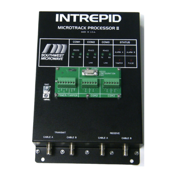
INTREPID MicroTrack II Manual Installing the MicroTrack™ Processor II (MTP II) The front panel of a MicroTrack Processor II with its key interface points is shown in Figure 7.1. Com Port 3 Green Com Port 1 Green LED’s for RS422 Data LED’s for RS232 Data... -
Page 62: Grounding The Mtp Ii
INTREPID MicroTrack II Manual The lead-in cables, power cables and data communications cables should be protected in either a PVC or galvanized steel conduit. The conduit can be installed directly in the ground below the enclosure or in a concrete base as illustrated in Figure 7.2. -
Page 63: Connecting The Pc Using Rs232
MTP II a 12 VDC or 24 VDC power supply can also be used. Section 3.1.12 lists optional power supplies available from Southwest Microwave, Inc. The size of the power cable wire gauge required depends on the distance between the power supply location and the MTP II, as well as the total number of auxiliary units (such as ROM II’s or other sensors being powered from the same cable). - Page 64 INTREPID MicroTrack II Manual MTP II on Perimeter To Enclosure COM 1 Tamper Switch RS232 CONFIGURATION PORT RS422 RS422 POWER/TAMPER COM 1 COM 2 Wire Gauge determined by distance from Power Supply To next device 22 or 24 Ga. wire Two (2) JB70A's Recommended.
-
Page 65: Connecting Sensor Cables To The Mtp Ii
INTREPID MicroTrack II Manual 7.8 Connecting Sensor Cables to the MTP II The sensor cable components include the sensor cable assemblies and the MicroTrack™ Terminations (MTT’s and MTI’s), as described in Section 3.1.2, 3.1.3 and 3.1.4. Each sensor cable assembly includes a factory-spliced lead-in cable with ferrite beads and a TNC connector for quick connection to the MicroTrack Processor II (MTP II), as shown in Figure 7.4. - Page 66 ...
-
Page 67: Alarm Reporting
INTREPID MicroTrack II Manual ALARM REPORTING There are three (3) ways to interface to the MicroTrack™ Processor II: (1) Relays, (2) Graphic Map, and (3) Serial Communications. 8.1 Relay Outputs There are two (2) controllers that can configure the MicroTrack Processor II to report alarm activity to relays only. - Page 68 ...
-
Page 69: Maintenance
INTREPID MicroTrack II Manual Maintenance The MicroTrack™ II system requires very little maintenance. The periodic maintenance which should be done at least every six (6) months includes: • Inspect the MTP II for any physical damage, water damage, corrosion and ingress of insects. - Page 70 ...
Need help?
Do you have a question about the INTREPID MicroTrack II and is the answer not in the manual?
Questions and answers