Table of Contents
Advertisement
Quick Links
Advertisement
Table of Contents

Subscribe to Our Youtube Channel
Related Manuals for King-Meter Digital II-LCD


Summary of Contents for King-Meter Digital II-LCD
- Page 1 KING-METER USERS GUIDE Digital II –LCD English...
-
Page 2: Table Of Contents
Contents Preface ....................1 Appearance and Size ................. 2 Material and Color ..............2 Function Summary and Button Definition ........3 Function Summary ..............3 Normal Display Area ..............4 Button Definition ............... 4 Operation Cautions ................5 Installation Instruction ..............5 Standard Operation ................ - Page 3 Password Enable ..............12 Password Modification ............12 Using Parameter Setting ............13 Wheel Diameter Setting ............14 Speed Limit Setting ..............14 Persona lized Parameter Setting............15 Persona lized Setting Password Input ........15 Battery Indicator Setting ............16 Pedal Assist Parameter Setting ..........
- Page 4 Recover Default Setting ..............25 FAQ and Questions ................26 Quality Warranty and Coverage ............27 Circuit Block Diagram ..............28 Software Version ................29 Appendix 1: Error Code ..............30 Appendix 2: Password Table............30 Appendix 3: Persona lized Parameter Setting ........31 Continue Appendix 3: ..............
-
Page 5: Preface
Dear users, To ensure better performance of your e-bike, please read through the Digital II-LCD product introduction carefully before using it. We will use the brief words to inform you of all the details(including hardware installation, setting and normal use of the display)when using our display. -
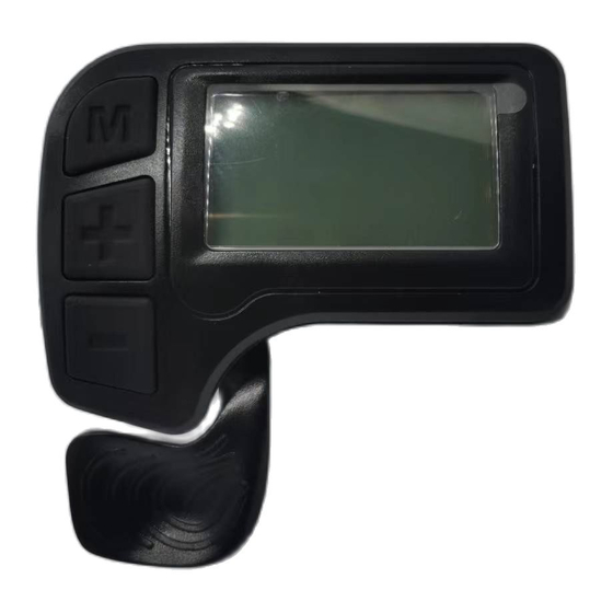
Page 6: Appearance And Size
Appearance and Size Material and Color Digital II-LCD housing material: PC. And the color of housing is black. Working temperature scope: -20℃—+60℃, the shell material can ensure normal use and good mechanical performance of the products Display Size and Installation Size(Unit:mm)... -
Page 7: Function Summary And Button Definition
Function Summary and Button Definition Function Summary Digital II-LCD offers plenty of functions and showing to meet your requirements. ◆Battery indicator ◆Speed(Including real time speed, Max speed and Average speed) ◆Distance (Including single Trip distance, ODO) ◆Trip time ◆Walk assist ◆Turn on Backlight... -
Page 8: Normal Display Area
Normal Display Area Digital II-LCD Normal display interface Button Definition The display with three buttons as below diagram, in the following introduction, is named as MODE, is named as is named as DOWN. -
Page 9: Operation Cautions
Operation Cautions Be careful during use, do not plug in and out the connector of display when electrified. Avoid collision. Please do not tear off the stickers to avoid water infusion. Please do not modify system parameters to avoid parameter disorder. Make the display repaired immediately when not working properly. -
Page 10: Standard Operation
Standard Operation Power On/Off Hold MODE button to start display and supply power to the controller, E-bike start to work. When at working state, press and hold MODE to shut off E-bike power. In the off state, the display no longer uses the battery's power supply;... -
Page 11: Walk Assist
After turning on display, it shows ODO distance (unit KM) .Press and hold MODE and DOWN together to switch the information, showing as ODO (unit KM) →single trip distance (unit KM) →single trip time →ODO (unit KM). Single trip Single trip time Walk Assist Press and hold DOWN to start walk assist status. -
Page 12: Turn On Backlight
Turn on Backlight Press and hold UP for 2 seconds to turn on the backlight of display, the e-bike headlight will be powered on at the same time. To turn on LCD backlight when lack of light or riding in night. Hold UP for 2 seconds again, LCD backlight turns off. -
Page 13: Battery Indicator
Battery Indicator The 5 battery bars represent the capacity of the battery. When the battery is in low voltage, battery frame will flash to notice that the battery needs to be recharged immediately. Battery voltage Flashing at low voltage Error code When the e-bike’s electronic system is wrongly working, display will show the error code. -
Page 14: Users Setting
Users Setting Preparation before Starting up Make sure all connectors tightened and the cables without damage, power on the e-bike. General Setting Press MODE button to start the display, then hold both UP and DOWN for 2 seconds to enter the setting menu. Trip Distance and Trip Time Clearance TC means trip distance clearance. -
Page 15: Backlight Brightness
Backlight Brightness BL means backlight. There are level 1, 2,3. Level 1 is the lowest brightness, Level 3 is highest brightness. The default level is 1. Press UP or DOWN to modify the backlight brightness. Exit Setting Shortly press MODE to confirm the input and enter into next setting. -
Page 16: Password Enable
interface. The factory default password is : 1234. Power-on password interface Password Enable Press UP/DOWN to select Y or N, and press MODE to confirm and enter Password modify interface. y = Power-on Password Enable n = Power-on Password Disable Password enable interface Password Modification PS means password. -
Page 17: Using Parameter Setting
Password modification interface Using Parameter Setting Hold both UP and DOWN for 2 seconds to enter normal setting interface. Then hold both DOWN and MODE for 2 seconds to enter Using parameter setting. On the screen shows “P 1”, this requests to input permission password. -
Page 18: Wheel Diameter Setting
Wheel Diameter Setting LD means wheel diameter. The set values are 16inch, 18 inch, 20 inch, 22 inch, 24 inch, 26inch, 700C, 28inch. Press UP and DOWN to select the corresponding wheel diameter of E-bike to ensure the accuracy of display speed and mileage. Press MODE to confirm and enter into Speed limit setting. -
Page 19: Personalized Parameter Setting
Personalized Parameter Setting Personalized parameter setting can match variety requirements in use. Setting items are: Battery indicator setting, PAS level setting, Over-current cut, PAS sensor setting, Speed sensor setting and Throttle function setting(optional) and System setting. In total six items. For the details, please see the Attached List 3. Personalized Setting Password Input Hold both UP and DOWN for more than 2 seconds to enter normal setting, then hold both UP and DOWN again to enter into... -
Page 20: Battery Indicator Setting
Option Select Page Battery Indicator Setting VOL means battery voltage. Each battery bar represents a voltage value. 5 voltage values MUST BE entered one by one. Take the first voltage for example, “1” on the screen means the first voltage, “28.0”... -
Page 21: Pedal Assist Parameter Setting
Pedal Assist Parameter Setting Pedal Assist Level Option SAC means pedal assist parameter setting. In Pedal assist level setting , there are 8 modes to select: 0-3, 1-3, 0-5, 1-5, 0-7, 1-7, 0-9, 1-9. Press UP/DOWN to select, press MODE to confirm and enter into the Pedal assist ratio setting. -
Page 22: Controller Over-Current Cut Setting
Pedal assistant ratio setting interface Controller Over-Current Cut Setting CUR means current. CUR value can be changed from 7.0A to 18.0A. Press UP/DOWN is to change the value of the current, and hold MODE to confirm the setting and turn back to personalized parameter setting interface. -
Page 23: Pedal Assist Sensor Setting
Pedal Assist Sensor Setting The Direction of Pedal Assist Sensor Setting Run means the running direction of pedal assist sensor. “run-F” means forward direction, while “run-b” means backward direction. Press UP/DOWN to select F or b, and press MODE to confirm and turn to PAS sensitivity setting. -
Page 24: Pas Sensor Proportion Parameter Setting
PAS Sensor Proportion Parameter Setting n means the proportion parameter of PAS. Press UP/DOWN to select the parameter, the more power, the more PAS feeling. Hold MODE to confirm and turn back to personalized parameter setting interface. Proportion parameter of PAS Speed Sensor Selection SPS means Speed sensor. -
Page 25: Throttle Function Setting (Optional)
Throttle Function Setting (optional) Throttle Walk Assist Enable/Disable(optional) HL means throttle walk assist. HL:N means function disable ,HL:Y means function enable . When HL=Y, use the throttle to realize walk assist state. Press UP/DOWN to select Y/N. If N is selected, press MODE to confirm and turn to throttle vector enable setting, otherwise there is no response. -
Page 26: System Setting
maximum speed. Press UP/DOWN to select Y or N, and hold MODE to confirm the selection and turn back to personalized parameter setting interface. Throttle Vector Enable/Disable interface System Setting Delay Time Setting of Battery Power DLY means delay time of battery power. Choose delay time 3/6/12s through pressing UP/DOWN, then shortly press MODE to confirm and enter the max speed limit setting. -
Page 27: Button Walk Assist Enable Setting
pressing UP/DOWN from 25-40 Km/h. Shortly press MODE to confirm and enter into Button walk mode enable setting. The default is 40Km/h. Max speed limit setting interface This setting parameter is the upper limit specified by the display manufacturer. Button Walk Assist Enable Setting PUS means button pushing walk assist. -
Page 28: Walk Assist Speed Setting
Walk Assist Speed Setting PU means Push (walk assist speed setting). Set the value to adjust walk assist speed to meet rider’s requirements. The scope is “20-35” by pressing UP/DOWN, shortly press MODE to confirm and enter into Slowly start up setting. Default value is 25(i.e. -
Page 29: Exit Setting
Exit Setting At the Personalized parameter setting state: shortly press MODE to confirm the input and enter into next setting; hold MODE for more than 2 seconds to save current parameter setting and exit the current setting; hold DOWN to cancel the current operation and exit without saving the current setting. -
Page 30: Faq And Questions
password inputted, press MODE to confirm. After recovering successfully, the display will automatically exit. Input recovery password interface In the recovery default, battery power, ODO and trip cannot be recovered, but starting up password can be recovered. FAQ and Questions Q: Why the display is not able to start up? A: Check the connector between display and controller. -
Page 31: Quality Warranty And Coverage
Quality Warranty and Coverage I. Warranty 1. Any quality problems in normal case and during guarantee period, our company will be responsible for the warranty. 2. The warranty time is 24 months after display out of the factory. Ⅱ. Other items The following items do not belong to our warranty scope. -
Page 32: Circuit Block Diagram
Circuit Block Diagram Table 1 : Standard connector cable sequence (display without throttle) Standard Wire color Definition sequence Power+ red(VCC) blue(K) Power of controller black(GND) green(RX) Receiving data yellow(TX) Transmitting data Notes: some displays are with waterproof cables, wires hidden inside the wire cover. -
Page 33: Software Version
Software Version This operating instruction is general-purpose software (version V1.0). Some version of the e-bike LCD may have slightly difference, which should depend on the actual use version. -
Page 34: Appendix 1: Error Code
Appendix 1: Error Code Code number Definition Abnormal current Throttle fault Motor phase problem Motor Hall defect Brake Failed Abnormal Communication Appendix 2: Password Table Display Password Setting Using parameter setting 0512 password (fixed) Default Starting up password 1234 (changeable) Personalized parameter 2962 setting password (fixed) -
Page 35: Appendix 3: Personalized Parameter Setting
Appendix 3: Personalized Parameter Setting Setting Display Details Battery Five battery power value power PAS level option PAS level PAS level proportion Limit current Current-limit PAS sensor direction PAS sensor sensitivity PAS sensor Speed Speed sensor magnet No. sensor... - Page 36 Continue Appendix 3: Setting Display Details Throttle walk assist enable setting Throttle function Throttle vector enable setting Time delay of battery Max speed setting Button walk assist enable setting System setting Walk assist speed setting Slowly startup setting...
-
Page 37: Appendix 4: Pedal Assist Proportion Default Value
Appendix 4: Pedal Assist Proportion default value Level Level Item 0-3/ 1-3 — — — — — — 0-5/ 1-5 100% — — — — 0-7/ 1-7 — — 0-9/ 1-9... - Page 38 KING-METER...
Need help?
Do you have a question about the Digital II-LCD and is the answer not in the manual?
Questions and answers