Table of Contents
Advertisement
Quick Links
Advertisement
Chapters
Table of Contents

Related Manuals for Blue Technix CM-BF537E

Summary of Contents for Blue Technix CM-BF537E
- Page 1 Hardware User Manual CM-BF537E V3.x...
- Page 2 Contact Bluetechnix Mechatronische Systeme GmbH Waidhausenstr. 3/19 A-1140 Vienna AUSTRIA/EUROPE office@bluetechnix.at http://www.bluetechnix.com Document No.: 100-1221-3.0 Document Revision 3 Date: 2010-02-02 CM‐BF537E ‐ Hardware User Manual 1 ...
-
Page 3: Table Of Contents
Environmental Specification ............................10 2.5.1 Temperature ................................10 2.5.2 Humidity ................................... 10 CM-BF537E (Connector Version) ............................11 Mechanical Outline ................................ 11 Footprint - Connector Version ............................ 11 Mount Options ................................. 13 Schematic Symbol (Signals of X1 and X2) ......................14 Connectors Pin Assignment .............................. - Page 4 Stand-alone Ethernet based MPEG Webcam ......................22 Design Services ................................23 Anomalies ....................................24 Production Report ..................................25 CM-BF537E (100-1221) ..............................25 CM-BF537E-I (100-1229) ............................... 25 Product Changes ................................. 26 Document Revision History .............................. 27 List of Figures and Tables ..............................27 CM‐BF537E ‐ Hardware User Manual ...
- Page 5 Edition 2008-09 © Bluetechnix Mechatronische Systeme GmbH 2008 All Rights Reserved. The information herein is given to describe certain components and shall not be considered as a guarantee of characteristics. Terms of delivery and rights of technical change reserved. We hereby disclaim any warranties, including but not limited to warranties of non-infringement, regarding circuits, descriptions and charts stated herein.
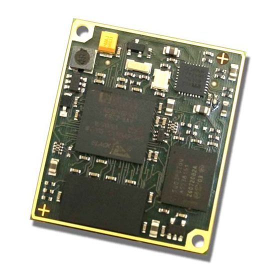
- Page 6 Blackfin Processor Module powered by Analog Devices' single core ADSP-BF533 processor; up to 600MHz, 32MB SDRAM, 2MB flash, 2x60 pin expansion connectors and a size of 36.5x31.5mm. CM-BF537E: Blackfin Processor Module powered by Analog Devices' single core ADSP-BF537 processor; up to 600MHz, 32MB SDRAM, 4MB flash, integrated TP10/100 Ethernet physical transceiver, 2x60 pin expansion connectors and a size of 36.5x31.5mm.
- Page 7 BF548DA-Lite is a low-cost starter development system including a VDSP++ Evaluation Software License. EXT-Boards: The following Extender Boards are available: EXT-BF5xx-AUDIO, EXT-BF5xx- VIDEO, EXT-BF5xx-CAM, EXT-BF5xx-EXP-TR, EXT-BF5xx-USB-ETH2, EXT-BF5xx- AD/DA, EXT-BF548-EXP and EXT-BF518-ETH. Furthermore, we offer the development of customized extender boards for our customers. Software Support: BLACKSheep: The BLACKSheep VDK is a multithreaded framework for the Blackfin processor...
-
Page 8: Introduction
1 Introduction The CM-BF537E is a tiny, high performance and low power DSP/RISC Core Module incorporating Analog Devices Blackfin family of processors. The special feature of this module is the on-board 10/100Mbit Ethernet interface which includes the physical transceiver chip. The module allows easy integration into high demanding very space and power limited applications. -
Page 9: Key Features
PPI (Parallel Port Interface) GPIO’s 1.2 Key Features The CM-BF537E is very compact and measures only 36.5x31.5mm Allows quick prototyping of product that comes very close to the final design Reduces development costs, faster time to market ... -
Page 10: Specification
PPI, SPORT0, UART1, UART2, SPI, TWI, CAN, GPIO Figure 2-1: Detailed Block Diagram Figure 2-1 shows a detailed block diagram of the CM-BF537E module. Other than the SDRAM control pins the CM-BF537E has all other pins of the Blackfin processor on its two main 60 pin connectors. -
Page 11: Memory Map
2.3 Memory MAP Memory Type Start Address End Address Size Comment FLASH Bank0 0x20000000 0x201FFFFF 4MB Micron Flash, (PF4 Flag low) PF48F2000P0ZBQ0 FLASH Bank1 0x20000000 0x201FFFFF (PF4 Flag high) SD‐RAM 0x00000000 0x01FFFFFF 32MB 16Bit Bus, Micron MT48LC16M16A2FG Table 2-1: Memory Map The maximum amount of memory addressable by a single asynchronous memory bank, of the Blackfin processor is 2MB. -
Page 12: Cm-Bf537E (Connector Version)
3 CM-BF537E (Connector Version) 3.1 Mechanical Outline TOP VIEW All dimensions are given in millimeters! Figure 3-1: Mechanical outline and Bottom Connectors (Top View) The mechanical outline represents a top view of the connectors placed at the bottom of the core board. -
Page 13: Figure 3-3: Recommended Footprint For The Core Module (Top View)
For the baseboard the following connectors have to be used: Part Baseboard Manufacturer Manufacturer Part No. X1,X2 Hirose FX8‐60S‐SV Table 3-1: Baseboard connector types The Connectors on the CM-BF537E are of the following type: Part Manufacturer Manufacturer Part No. X1,X2 3mm height FX8‐60P‐SV Hirose Table 3-2: Module connector types... -
Page 14: Mount Options
3.3 Mount Options The mount options of the Core Module are shown in Figure 3-4. Figure 3-4: Core Module (component side) Mount Option Flash Comment MO1 2MB PF4 available on pin 7 on connector X1 MO2 4MB default MO3 8MB PF5 not available on connector X1 Table 3-3 Mount Options CM‐BF537E ‐ Hardware User Manual 13 ... -
Page 15: Schematic Symbol (Signals Of X1 And X2)
PF10 / SPI_CS1 PF4 / TMR5 / SPI_CS6 (or OPEN) PF6 / TMR3 / SPI_CS4 PF5 / TMR4 / SPI_CS5 PF5 / TMR4 / SPI_CS5 Vin 3V3 Vin 3V3 CM-BF537E ABE0 PG0 / PPI1D0 ABE1 PG1 / PPI1D1 LED_SPEED PG2 / PPI1D2... -
Page 16: Connectors Pin Assignment
4 Connectors Pin Assignment 4.1 Connector X1 – (1-60) Pin No. Signal IO Type 1 RSCLK0 / TACLK2 2 DR0PRI / TACLK4 I 3 TSCLK0 / TACLK1 I/O 4 DT0PRI / SSEL2 O 5 CLK_out O 6 SDA I/O 7 PF4 / TMR5 / SSEL6: MO1* I/O ... -
Page 17: Table 4-1: Connector X1 Pin Assignment
41 PPI1Clk / PF15 / TMRCLK I/O 42 PPI1Sy2 / PF8 / TMR1 I/O 43 PG15 / PPI1D15 / DT1PRI I/O 44 PG13 / PPI1D13 / TSCLK1 I/O 45 PG11 / PPI1D11 / RFS1 I/O 46 PG9 / PPI1D9 / DT1SEC I/O 47 PG7 / PPI1D7 I/O 48 PG5 / PPI1D5 I/O 49 PG3 / PPI1D3 I/O 50 PG1 / PPI1D1 I/O 51 GND PWR 52 GND PWR 53 PF5 / TMR4 / SSEL5 I/O 54 PF6 / TMR3 / SSEL4 ... -
Page 18: Connector X2 - (61-120)
4.2 Connector X2 – (61-120) Pin No. Signal IO Type 61 A1 62 A3 63 A5 64 A7 65 A9 66 A11 67 A13 68 A15 69 A17 70 A19 71 ABE1 ¯¯¯¯/SDQM0 72 LED_ACT 73 GND ‐ 74 RX+ ... -
Page 19: Pin Out Description
Indicates Ethernet activity 73 GND AGND (use as GND for Ethernet 74 RX+ Ethernet receive + 75 RX‐ Ethernet receive ‐ 106 VA25 Ethernet transformer voltage reference 107 TX‐ Ethernet transmit ‐ 108 TX+ Ethernet transmit + 109 LED_FD Full duplex LED, High = Full duplex active, 110 LED_SPEED 10Mbps = Low, 100Mbps = High Table 4-3: Pin description of all non Processor Pins on the CM-BF537E CM‐BF537E ‐ Hardware User Manual 18 ... -
Page 20: Reset Circuit
4.4 Reset circuit The reset of the flash and the processor are connected to a power monitoring IC. The output can be used as power on reset for external devices, see Figure 4-1. 3.3V RESET of Flash TCM809SENB713 RESET RESET of ADSP-BF5xx 470R Core Module External... -
Page 21: Software Support
It contains a boot-loader for flashing the Core Module via the serial port. http://192.168.0.10 By default the BLACKSheep for the CM-BF537E has a web server. By typing you can see a standard web page installed on the Core Module. -
Page 22: Application Examples
Application Examples 6.1 Sample Schematic In this minimum configuration the CM-BF537E is used as a high performance network connected processor module. RSCLK0 / TACLK2 ADP3338 RFS0 / TACLK3 5.0V 3.3V DR0PRI / TACLK4 DR0SEC / TACI0 / CAN_Rx TSCLK0 / TACLK1... -
Page 23: Stand-Alone Ethernet Based Mpeg Webcam
6.2 Stand-alone Ethernet based MPEG Webcam The CM-BF537E module can be used as a stand-alone module for a camera system requiring only power supply and the direct attachment of a compatible video camera. An extender board including a camera is available at Bluetechnix (EXT-BF5xx-Camera). -
Page 24: Design Services
Designator Value Type Description Quantity C3, C4, C5, C6, C8 Capacitor C7, C9 10uF Capacitor Cam1 OV7660FSx Camera module CM-BF537 green SMD LED DC-8 Power connector DC-8 HFJ11-2250E RJ45 with transformer R1,R3 Resistor R7, R8, R9 220R Resistor S1, S2 Switch ADP3338 Low dropout regulator... -
Page 25: Anomalies
Anomalies For the latest information regarding anomalies for this product, please consult the product home page: http://www.bluetechnix.com/goto/cm-bf537e CM‐BF537E ‐ Hardware User Manual 24 ... -
Page 26: Production Report
Production Report 8.1 CM-BF537E (100-1221) Version Component Type V3.0.1 Processor ADSP-BF537 KBCZ-6A (Rev 0.3) MT48LC16M16A2BG-75 IT:D FLASH PF48F2000P0ZBQ0 Mount Option MO2 see chapter 3.3 Table 8-1: Production Report CM-BF537E 8.2 CM-BF537E-I (100-1229) Table 8-2: Production Report CM-BF537E-I CM‐BF537E ‐ Hardware User Manual 25 ... -
Page 27: Product Changes
Product Changes For the latest product change information please consult the product web-page at: http://www.bluetechnix.com/goto/cm-bf537e CM‐BF537E ‐ Hardware User Manual 26 ... -
Page 28: Document Revision History
Table 4-1: Connector X1 pin assignment ........................... 16 Table 4-2: Connector X2 pin assignment ........................... 18 Table 4-3: Pin description of all non Processor Pins on the CM-BF537E ................. 18 Table 4-4: Parts List RJ45 .................................. 19 Table 7-1: Bill of Material of Sample Circuit ..........................21 Table 7-2: Bill of Materials of a Stand-alone Ethernet based MPEG Webcam ..............
Need help?
Do you have a question about the CM-BF537E and is the answer not in the manual?
Questions and answers