Table of Contents
Advertisement
Quick Links
Advertisement
Chapters
Table of Contents

Related Manuals for Blue Technix CM-BF527

Summary of Contents for Blue Technix CM-BF527
- Page 1 Hardware User Manual CM-BF527 v2.x...
- Page 2 Contact Bluetechnix Mechatronische Systeme GmbH Lainzerstraße 162/3 A-1130 Vienna AUSTRIA/EUROPE office@bluetechnix.at http://www.bluetechnix.com Document No.: 100-1251-2.2 Document Revision 1 Date: 2010-06-28 Blackfin CM-BF527 Hardware User Manual...
-
Page 3: Table Of Contents
Reset circuit..................................19 RJ45 schematic ................................19 Software Support ..................................20 BLACKSheep ..................................20 uClinux ....................................20 Application Examples ................................21 Sample Schematic ................................21 Blackfin CM-BF527 Hardware User Manual... - Page 4 Design Services ................................23 Anomalies ....................................24 Product Changes ..................................25 Production Report..................................25 Document Revision History ..............................25 List of Figures and Tables ..............................26 Blackfin CM-BF527 Hardware User Manual...
- Page 5 Permanent damage may occur on devices subjected to high-energy discharges. Proper ESD precautions are recommended to avoid performance degradation or loss of functionality. Unused Core Modules and Development Boards should be stored in the protective shipping Blackfin CM-BF527 Hardware User Manual...
-
Page 6: Blackfin Products
36.5x31.5mm. eCM-BF561: Blackfin Processor Module powered by Analog Devices' dual core ADSP- BF561 processor; up to 2x 600MHz, 128MB SDRAM, 8MB flash, 2x100 pin expansion connectors and a size of 44x33mm. Blackfin CM-BF527 Hardware User Manual... -
Page 7: Blackfin Design Service
Keep up-to-date with all the changes to the Bluetechnix product line and software updates at: http://www.bluetechnix.com BLACKFIN Design Service Based on more than five years of experience with Blackfin, Bluetechnix offers development assistance as well as custom design services and software development. Blackfin CM-BF527 Hardware User Manual... -
Page 8: Introduction
1 Introduction The CM-BF527 is a member of Blackfin based core modules incorporating the consumer temperature version of the ADSP-BF527 (optional also ADSP-BF525 or ADSP-BF522). It is backwards compatible to the CM-BF537E for most of its interfaces and can be used as a replacement module on any Bluetechnix development or evaluation Board. -
Page 9: Key Features
Boot Mode GPIO’s 1.2 Key Features The CM-BF527 is a low cost compact core module and measures only 36x31mm Allows quick prototyping of product that comes very close to the final design Reduces development costs, faster time to market ... -
Page 10: Specification
Figure 2-1 shows a detailed block diagram of the CM-BF527 module. Besides the SDRAM control pins and the Pins used by the Ethernet Physical Transceiver (Port H) the CM-BF527 has all other pins of the Blackfin processor on its two main 60 pin connectors. -
Page 11: Memory Map
15 Boot from 8‐Bit Host DMA Table 2-1: Boot Mode CM-BF527 Connect BMODE0 to Vcc and leave BMODE1, BMODE2 and BMODE3 pins open for Boot Mode 0001 equals to 8 or 16 bit PROM/FLASH boot mode. This is the default boot mode of the BLACKSheep software and uClinux. -
Page 12: Electrical Specification
Processor running at 600MHz, Core Voltage 1.2V, SDRAM 20% bandwidth utilization at 130MHz, Ethernet TX/RX active: TBD 2.5 Environmental Specification 2.5.1 Temperature Operating at full 600MHz: 0 to + 70° C 2.5.2 Humidity Operating: 10% to 90% (non condensing) Blackfin CM-BF527 Hardware User Manual... -
Page 13: Cm-Bf527
Figure 3-1: Mechanical outline and Components on top side Take 0.5mm as a tolerance for the boarder of the board since it is broken out from a multi-board panel and some additional boarder may remain. The module is shipped with two 60pin connectors. Blackfin CM-BF527 Hardware User Manual... -
Page 14: Figure 3-2: Side View With Connector Mounted, 0.5Mm Tolerances
BF527 Core Module. All dimensions are given in millimeters! Figure 3-3: Mechanical outline and Bottom Connectors (top view The mechanical outline represents a TOP VIEW of the connectors placed at the bottom of the core board. Blackfin CM-BF527 Hardware User Manual... -
Page 15: Footprint
Note the additional connector X1 (FFC-20) is not supported yet and used for AUDIO functionality in future revisions with the –C variant of the ADSP-BF527 Chip. X1 is not described in this document any further. The connectors on the CM-BF527 are of the following type: Part Manufacturer ... -
Page 16: Schematic Symbol (Signals Of X2 And X3)
3.4 Connector Pin Assignments In the following tables you will find pin assignments for the Core Module connectors. Most pins are directly connected to the Blackfin processor. If not, please read the Notes below the table. Blackfin CM-BF527 Hardware User Manual... -
Page 17: Connector X2 - (1-60)
I ‐ 4k7 pull down 31 ˉˉˉˉ 32 I – 10k pull up 33 34 Bmode2 I ‐10k pull down 35 Bmode3 I ‐10k pull down 36 Bmode1 I ‐10k pull down 37 PG3 / SPIMISO / DR0SECA 38 PG7 / TMR3 / DR0PRIA / UART0TX 39 PG1 / SPISS ˉˉˉˉˉ / SPISEL1 ˉˉˉˉˉˉˉˉ 40 PG12 / DMAR1 / UART1TXA / H_ACK 41 PPICLK / TMRCLK 42 PG5 / TMR1 / PPIFS2 Blackfin CM-BF527 Hardware User Manual... -
Page 18: Connector X3 - (61-120)
64 65 66 A11 67 A13 68 A15 69 A17 70 A19 71 ABE1 ˉˉˉˉ 72 LED_ACT 73 GND Power 74 RX+ IO – 49R9 pull up to 2V5 75 RX‐ IO – 49R9 pull up to 2V5 76 ARDY 77 USBD+ 78 SCLK Blackfin CM-BF527 Hardware User Manual... -
Page 19: Table 3-4: Connector X3 Pin Assignment
IO – 49R9 pull up to 2V5 108 TX+ IO – 49R9 pull up to 2V5 109 LED_FD 110 LED_SPEED 111 ABE0 ˉˉˉˉ 112 A18 113 A16 114 A14 115 A12 116 A10 117 118 119 120 Table 3-4: Connector X3 pin assignment Blackfin CM-BF527 Hardware User Manual... -
Page 20: Reset Circuit
External Figure 3-7: Schematic for RJ45 Connection Designator Value Type Description Quantity X1 RJLBC‐060TC1 RJ45 with transformer 1 R4, R5 27R Resistor 2 R8, R9 220R Resistor 2 V1, V2 USBLC6‐2P6 TSV‐Diode 2 Table 3-5: Parts List RJ45 Blackfin CM-BF527 Hardware User Manual... -
Page 21: Software Support
The Core Module is delivered with a pre-flashed basic version of the BLACKSheep VDK multithreaded framework. It contains a boot-loader for flashing the Core Module via the serial port. The BLACKSheep for the CM-BF527 contains also a web server. By typing http://192.168.0.10 you can see a standard web page installed on the Core Module. -
Page 22: Application Examples
5 Application Examples 5.1 Sample Schematic In this minimum configuration the CM-BF527 is used as a high performance network connected processor module. ADP3338 5.0V 3.3V VppOTP PH10/ND_CE/ERxD2/HOST_D10 PH11/ND_WE/ETxD3/HOST_D11 PH12/ND_RE/ERxD3/HOST_D12 PH13/ND_BUSY/ERxCLK/HOST_D13 PH14/ND_CLE/ERxDV/HOST_D14 PH15/ND_ALE/COL/HOST_D15 PG0/HWAIT CLK_out 3.3V PH9/SPISEL5/ETxD2/HOST_D9/TACLK3 PG9/TMR5/RSCLK0A/TACI5 PG10/TMR6/TSCLK0A/TACI6 PG11/TMR7/HOST_WR 10uF... -
Page 23: Stand-Alone Ethernet Based Mpeg Webcam
5.2 Stand-alone Ethernet based MPEG Webcam The CM-BF527 module can be used as a stand-alone module for a camera system requiring only power supply and the direct attachment of a compatible video camera. An extender board including a camera is available at Bluetechnix (EXT-BF5xx-CAM). -
Page 24: Design Services
1 U3 XC6204B182MR XC6204 LDO regulators 1 CM1 CM‐BF537 1 Table 5-2: Bill of Material of a Stand-alone Ethernet based MPEG Webcam 5.3 Design Services Bluetechnix offers custom design services and software development. Blackfin CM-BF527 Hardware User Manual... -
Page 25: Anomalies
6 Anomalies For the latest information regarding anomalies for this product, please consult the product home page: http://www.bluetechnix.com/goto/cm-bf527 V2.2 Table 6-1: Anomalies Blackfin CM-BF527 Hardware User Manual... -
Page 26: Product Changes
Changes V2.2 Initial Preliminary Version Table 7-1: Product Changes 8 Production Report For Production Report please see: https://support.bluetechnix.at/wiki/Revision_Report_CM-BF527 9 Document Revision History Version Date Document Revision 2010-06-28 Copied from CM-BF527 V1.x Table 9-1: Revision History Blackfin CM-BF527 Hardware User Manual... -
Page 27: List Of Figures And Tables
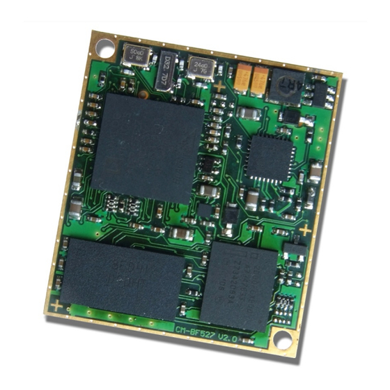
List of Figures and Tables Figures Figure 1-1: Main components of the CM-BF527 Core Module ......... 7 Figure 2-1: Detailed Block Diagram ................... 9 Figure 2-2: IO pin to flash address pin assignment ............11 Figure 3-1: Mechanical outline and Components on top side ........12 ...
Need help?
Do you have a question about the CM-BF527 and is the answer not in the manual?
Questions and answers