Carrier UC Open XP Installation And Start-Up Instructions Manual
For 39mn,mw indoor and weathertight outdoor air handlers
Hide thumbs
Also See for UC Open XP:
- Installation and startup manual (50 pages) ,
- Installation and startup manual (44 pages)
Table of Contents
Advertisement
Quick Links
Installation and Start-Up Instructions
TABLE OF CONTENTS
SAFETY CONSIDERATIONS . . . . . . . . . . . . . . . . . . . . . . 1
INTRODUCTION . . . . . . . . . . . . . . . . . . . . . . . . . . . . . . . 2-10
General . . . . . . . . . . . . . . . . . . . . . . . . . . . . . . . . . . . . . . . . . . 2
Service Area Requirements . . . . . . . . . . . . . . . . . . . . . . 2
Electrical Requirements. . . . . . . . . . . . . . . . . . . . . . . . . . 2
INSTALLATION . . . . . . . . . . . . . . . . . . . . . . . . . . . . . . . 10-12
UC Open XP Control System . . . . . . . . . . . . . . . . . . . . 10
Control System Wiring . . . . . . . . . . . . . . . . . . . . . . . . . . 10
To Wire the Controller to the Network . . . . . . . . . . . 11
FIELD WIRING . . . . . . . . . . . . . . . . . . . . . . . . . . . . . 12-22
Wiring Requirements. . . . . . . . . . . . . . . . . . . . . . . . . . . . 12
Supply-Air Temperature Sensor . . . . . . . . . . . . . . . . . 12
Fan Status Switch . . . . . . . . . . . . . . . . . . . . . . . . . . . . . . . 13
Fan Status Switch Adjustment. . . . . . . . . . . . . . . . . . . 14
Fan Status Switch Field Installation . . . . . . . . . . . . . 14
Return-Air Temperature Sensor . . . . . . . . . . . . . . . . . 15
Outdoor-Air Temperature Sensor . . . . . . . . . . . . . . . . . 15
Mixed-Air Temperature Sensor . . . . . . . . . . . . . . . . . . 15
Low-Temperature Thermostat . . . . . . . . . . . . . . . . . . . 15
Preheat Temperature Sensor . . . . . . . . . . . . . . . . . . 15
Filter Status Switch. . . . . . . . . . . . . . . . . . . . . . . . . . . . . . 16
Steam/Water Valves . . . . . . . . . . . . . . . . . . . . . . . . . . . . . 18
Field-Supplied Two-Position Water Valves . . . . . . . 18
Mixing Box Damper Actuators . . . . . . . . . . . . . . . . . . . 18
Exhaust Damper Actuator . . . . . . . . . . . . . . . . . . . . . . . 19
Face and Bypass Damper Actuator . . . . . . . . . . . . . . 19
Variable-Frequency Drives . . . . . . . . . . . . . . . . . . . . . . 19
DX Cooling Control. . . . . . . . . . . . . . . . . . . . . . . . . . . . . . 19
Electric Heat Control . . . . . . . . . . . . . . . . . . . . . . . . . . . . 21
Electric Heat Sequencer. . . . . . . . . . . . . . . . . . . . . . . . . . 21
SCR Controller. . . . . . . . . . . . . . . . . . . . . . . . . . . . . . . . . . . 21
Vernier Controller . . . . . . . . . . . . . . . . . . . . . . . . . . . . . . . . 21
TROUBLESHOOTING. . . . . . . . . . . . . . . . . . . . . . . . . 22,23
Communication LEDs . . . . . . . . . . . . . . . . . . . . . . . . . . . . 22
UC OPEN XP SPECIFICATIONS. . . . . . . . . . . . . . . . . . 23
UC OPEN XP IO SPECIFICATIONS . . . . . . . . . . . . . . . 24
SAFETY CONSIDERATIONS
IMPORTANT: This equipment generates, uses, and
can radiate radio frequency energy and if not installed
and used in accordance with these instructions may
cause radio interference. The equipment has been tested
and complies with the limits of a Class A computing
device as defined by FCC (Federal Communications
Commission) regulations, Subpart J of Part 14, which
are designed to provide reasonable protections against
such interference when operated in a commercial
environment.
Installation and start-up of air-handling equipment can be
hazardous due to system pressure, rotating parts, and electrical
Manufacturer reserves the right to discontinue, or change at any time, specifications or designs without notice and without incurring obligations.
Catalog No. 04-53390010-01
UC Open XP/UC Open XP IO
Weathertight Outdoor Air Handlers
components. Only trained and qualified service personnel
should install, start-up or service air-conditioning equipment.
Page
precautions in the literature, tags and labels attached to the unit,
and other safety precautions that may apply.
Standards Institute) Z223.1 or latest version. Wear a hard hat,
safety glasses, and work gloves.
Printed in U.S.A.
for 39MN,MW Indoor and
When working on air-conditioning equipment, observe
Follow all safety codes, including ANSI (American National
WARNING
Disconnect all power to the unit, then lock out and safety
tag all disconnects before performing maintenance or
service. Unit may automatically start if power is not
disconnected. Electrical shock and personal injury could
result.
WARNING
DO NOT USE TORCH to remove any component. System
contains oil and refrigerant under pressure.
To remove a component, wear protective gloves and gog-
gles and proceed as follows:
a. Shut off electrical power to unit.
b. Recover refrigerant to relieve all pressure from sys-
tem using both high-pressure and low pressure ports.
c. Traces of vapor should be displaced with nitrogen
and the work area should be well ventilated. Refrig-
erant in contact with an open flame produces toxic
gases.
d. Cut component connection tubing with tubing cutter
and remove component from unit. Use a pan to catch
any oil that may come out of the lines and as a gage
for how much oil to add to the system.
e. Carefully unsweat remaining tubing stubs when nec-
essary. Oil can ignite when exposed to torch flame.
Failure to follow these procedures may result in personal
injury or death.
CAUTION
DO NOT re-use compressor oil or any oil that has been
exposed to the atmosphere. Dispose of oil per local codes
and regulations. DO NOT leave refrigerant system open to
air any longer than the actual time required to service the
equipment. Seal circuits being serviced and charge with
dry nitrogen to prevent oil contamination when timely
repairs cannot be completed. Failure to follow these proce-
dures may result in damage to equipment.
FOR YOUR SAFETY
Do not store or use gasoline or other flammable vapors and
liquids in the vicinity of this or any other appliance.
Form 39M-12SI
Pg 1
10-12
Replaces: 39M-3SI
Advertisement
Table of Contents

Related Manuals for Carrier UC Open XP


Summary of Contents for Carrier UC Open XP
-
Page 1: Table Of Contents
INSTALLATION ....... 10-12 UC Open XP Control System ....10 WARNING Control System Wiring . -
Page 2: Introduction
240 vac powered. When ordered along with a 39M unit, the UC Open XP is All factory-supplied and installed accessories are powered installed inside a control box in its own control plenum or ex- by factory-installed transformers. - Page 3 SUPPLY AIR TEMP (SAT) MIXED AIR TEMP SENSOR LOW TEMP (MAT) SENSOR THERMOSTAT (LTT OR FREEZESTAT) a33-9293 CONTROLLER AND/OR DAMPER ACTUATORS ELECTRIC HEATER TERMINAL STRIP FILTER STATUS (EA, RA, OA) CONTROL BOARD SWITCH (FLTS) MOUNTED IN OWN PLENUM AND SEQUENCER OR EXTERNAL TO UNIT Fig.
- Page 4 Fig. 4 — UC Open XP Control Box Components...
- Page 6 a39-4366 Fig. 6 — Controller Wiring Schematic...
- Page 7 Table 1 — Sensor Only Wire Designations CONNECTION WIRE LENGTH “B” END WIRE WIRE NO. WIRE PART NO. “A” END WIRE LABEL “A” END TERM WIRE COLOR “B” END TERM DEVICE (in.) LABEL BROWN J1-1 39MA51007701 CB1-2 T1 24Vac BROWN J1-1 Power 39MA51007702...
- Page 8 Table 2 — UC Open XP Wire Designations DEVICE / CHANNEL # / CABLE # WIRE COLOR TERMINAL SIGNAL WHITE TB2-1 DRY CONTACT DI FILTER STATUS SWITCH (CHANNEL # UI-1) CABLE #3 BLACK TB2-2 SIGNAL GROUND WHITE TB2-10 10K THERMISTOR AI...
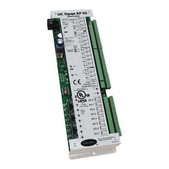
- Page 9 Local Rnet Access Rnet + Rnet + Rnet - Rnet - + 12V + 12V Sense Xnet Xnet - Remote Xnet + Expansion Open Energy Management Equipement BACnet Port a39-4347 Fig. 7 — UC Open XP Input and Output Terminals...
-
Page 10: Installation
On the UC Open XP, there is a power plug, a plug to con- shipped and/or installed in pieces. nect the module to optional I/O modules within the control... -
Page 11: To Wire The Controller To The Network
5. Set DIP switches 1 and 2 to the appropriate baud rate. See shields must be connected to ground at the lightning suppressor the MSTP baud diagram on the UC Open XP. The default in each building where the cable enters or exits the building baud rate is 76.8 kbps. -
Page 12: Component Installation And Field Wiring
) sensors and enthalpy and humidity sensors please see the 39M Controls Application Data. For installation and wiring instructions for these sensors please see the Carrier Sensor Installation Guide. A39-4356 Supply-Air Temperature Sensor (Fig. 14) — SAT sensor is factory installed and wired when either of the "Factory Wired"... -
Page 13: Fan Status Switch
Table 6 — Recommended Sensor and Device Wiring WIRE TYPE BELDEN PART NO. CAROL PART NO. ALPHA PART NO. 300-v, Non-Plenum, 60 C Minimum (CM) 9740 C6101 (or C5460*) 1897C 2-Conductor, 18 AWG Cable 8489 C2404 (or C5084*) 1898/4C 4-Conductor, 18 AWG Cable 8772 C2528 2413C/5463... -
Page 14: Fan Status Switch Adjustment
2. If the Blue LED is on, slowly adjust the potentiometer (labeled as "TRP ADJ" in Fig. 17) clockwise until the RED LED just turns on and stop immediately. The trip point is now set at the normal operating load current. 2.001 OUTPUT:1.0 36.0Vac/Vdc... -
Page 15: Return-Air Temperature Sensor
The UC Open XP control will stop the fan if damaging conditions are detected. If field installed, the LTT should be done so on the entering air side of the first cooling coil in the equipment. -
Page 16: Filter Status Switch
The filter status switch is factory installed in a filter or filter Filter Status Switch (P/N 33AMSENFLT000) — mixing box section if ordered in the AHUBuilder ® program The filter status differential pressure switch (FLTS) is a snap when either of the "Factory Wired" control options is selected. action SPDT type switch. - Page 17 Fig. 21 — Low-Temperature Thermostat NOTE: MOUNTING OF SENSOR COIL FIN COIL FINS AIRFLOW AND CAPILLARY TUBING TO BE ON LEAVING AIR SIDE OF SPRING CLIP FLOW COIL (DOWNSTREAM). CAPILLARY TUBE ON LEAVING AIR SIDE CAPILLARY TUBE DETAIL “A” TEMPERATURE THERMOSTAT SPRING CLIPS...
-
Page 18: Steam/Water Valves
As installed from the factory it provides spring return closing of the outdoor-air damper on loss of power. Field-Supplied Two-Position Water Valves — The UC Open XP control supports two-position water valves CAUTION for heating or CV cooling applications, although it is not rec-... -
Page 19: Exhaust Damper Actuator
These sensors are generally wired directly to the condenser's terminations of face and bypass heating and cooling actuators. control module, however they may pass the necessary signal to the condenser's controller via the UC Open XP and the BAC- Variable-frequency Variable-Frequency Drives —... - Page 20 ANTI-ROTATION STRAP (DOWNSTREAM COMPONENT) ACTUATOR (DOWNSTREAM (DOWNSTREAM (DOWNSTREAM ACTUATOR COMPONENT) COMPONENT) COMPONENT) CONTROL CABLE AIRFLOW AIRFLOW AIRFLOW AIRFLOW LINKAGE MIXED SENSOR (Top Only) (Top & Rear) (Top & Bottom) (Rear & Bottom) (DOWNSTREAM (DOWNSTREAM COMPONENT) COMPONENT) AIRFLOW AIRFLOW (Rear Only) (Bottom Only) A39-4365 TOP VIEW...
-
Page 21: Electric Heat Control
The SCR controller is installed in the electric heater control Electric heaters can be con- Electric Heat Control — box as shown in Fig. 28. trolled via an electric heat sequencer, SCR controller or Vernier controller as described below. The SCR controller is designed to receive a 0 to 10 vdc, 4 to 20 mA or 0 to 135 ohm control signal. -
Page 22: Troubleshooting
If you have problems mounting, wiring, or addressing the should reflect communication traffic based on the baud rate set. UC Open XP or the UC Open XP IO, contact Carrier Technical The higher the baud rate the more solid the LEDs become. See Support. -
Page 23: Uc Open Xp Specifications
SPECIFICATION DESCRIPTION Lights when power is being supplied to the Maximum Number of Control expander. Programs* NOTE: The UC Open XP is protected by Maximum Number of BACnet 1050 Power internal solid-state polyswitches on the Objects* incoming power and network connections. -
Page 24: Uc Open Xp Io Specifications
UC OPEN XP IO SPECIFICATIONS SPECIFICATION DESCRIPTION Power 24 vac ± 10%, 50-60 Hz 13 VA Power Consumption 26 vdc (25 V min, 30 V max) Single Class 2 source only, 100 VA or less IN 1-8 are binary only and sup-...
Need help?
Do you have a question about the UC Open XP and is the answer not in the manual?
Questions and answers