Table of Contents
Advertisement
LOVATO ELECTRIC S.P.A.
24020 GORLE (BERGAMO) ITALIA
VIA DON E. MAZZA, 12
TEL. 035 4282111
L
E
E-mail info@
ovato
lectric.com
L
E
Web
www.
ovato
lectric.com
WARNING!
– Carefully read the manual before the installation or use.
– This equipment is to be installed by qualified personnel, complying to current standards, to avoid
damages or safety hazards.
– Before any maintenance operation on the device, remove all the voltages from measuring and supply inputs and short-
circuit the CT input terminals.
– The manufacturer cannot be held responsible for electrical safety in case of improper use of the equipment.
– Products illustrated herein are subject to alteration and changes without prior notice. Technical data and descriptions
in the documentation are accurate, to the best of our knowledge, but no liabilities for errors, omissions or
contingencies arising there from are accepted.
– A circuit breaker must be included in the electrical installation of the building. It must be installed close by the
equipment and within easy reach of the operator. It must be marked as the disconnecting device of the equipment:
IEC /EN 61010-1 § 6.11.2.
– Clean the device with a soft dry cloth; do not use abrasives, liquid detergents or solvents.
ATTENTION !
– Lire attentivement le manuel avant toute utilisation et installation.
– Ces appareils doivent être installés par un personnel qualifié, conformément aux normes en vigueur en
matière d'installations, afin d'éviter de causer des dommages à des personnes ou choses.
– Avant toute intervention sur l'instrument, mettre les entrées de mesure et d'alimentation hors tension et court-circuiter
les transformateurs de courant.
– Le constructeur n'assume aucune responsabilité quant à la sécurité électrique en cas d'utilisation impropre du
dispositif.
– Les produits décrits dans ce document sont susceptibles d'évoluer ou de subir des modifications à n'importe quel
moment. Les descriptions et caractéristiques techniques du catalogue ne peuvent donc avoir aucune valeur
contractuelle.
– Un interrupteur ou disjoncteur doit être inclus dans l'installation électrique du bâtiment. Celui-ci doit se trouver tout
près de l'appareil et l'opérateur doit pouvoir y accéder facilement. Il doit être marqué comme le dispositif
d'interruption de l'appareil : IEC/ EN 61010-1 § 6.11.2.
– Nettoyer l'appareil avec un chiffon doux, ne pas utiliser de produits abrasifs, détergents liquides ou solvants.
ACHTUNG!
– Dieses Handbuch vor Gebrauch und Installation aufmerksam lesen.
– Zur Vermeidung von Personen- und Sachschäden dürfen diese Geräte nur von qualifiziertem
Fachpersonal und unter Befolgung der einschlägigen Vorschriften installiert werden.
– Vor jedem Eingriff am Instrument die Spannungszufuhr zu den Messeingängen trennen und die Stromwandler
kurzschlie en.
– Bei zweckwidrigem Gebrauch der Vorrichtung übernimmt der Hersteller keine Haftung für die elektrische Sicherheit.
– Die in dieser Broschüre beschriebenen Produkte können jederzeit weiterentwickelt und geändert werden. Die im
Katalog enthaltenen Beschreibungen und Daten sind daher unverbindlich und ohne Gewähr.
– In die elektrische Anlage des Gebäudes ist ein Ausschalter oder Trennschalter einzubauen. Dieser muss sich in
unmittelbarer Nähe des Geräts befinden und vom Bediener leicht zugänglich sein. Er muss als Trennvorrichtung für das
Gerät gekennzeichnet sein: IEC/ EN 61010-1 § 6.11.2.
– Das Gerät mit einem weichen Tuch reinigen, keine Scheuermittel, Flüssigreiniger oder Lösungsmittel verwenden.
ADVERTENCIA
– Leer atentamente el manual antes de instalar y utilizar el regulador.
– Este dispositivo debe ser instalado por personal cualificado conforme a la normativa de instalación
vigente a fin de evitar daños personales o materiales.
– Antes de realizar cualquier operación en el dispositivo, desconectar la corriente de las entradas de alimentación y
medida, y cortocircuitar los transformadores de corriente.
– El fabricante no se responsabilizará de la seguridad eléctrica en caso de que el dispositivo no se utilice de forma
adecuada.
– Los productos descritos en este documento se pueden actualizar o modificar en cualquier momento. Por consiguiente,
las descripciones y los datos técnicos aquí contenidos no tienen valor contractual.
– La instalación eléctrica del edificio debe disponer de un interruptor o disyuntor. Éste debe encontrarse cerca del
dispositivo, en un lugar al que el usuario pueda acceder con facilidad. Además, debe llevar el mismo marcado que el
interruptor del dispositivo (IEC/ EN 61010-1 § 6.11.2).
– Limpiar el dispositivo con un trapo suave; no utilizar productos abrasivos, detergentes líquidos ni disolventes.
UPOZORNĚNÍ
AVERTIZARE!
GB
INTERFACE PROTECTION SYSTEM
Compliant with
VDE-AR-N 4105 and VDE V 0126-1-1
application guides
Instruction manual
PMVF 80
ATTENZIONE!
– Leggere attentamente il manuale prima dell'utilizzo e l'installazione.
– Questi apparecchi devono essere installati da personale qualificato, nel rispetto delle vigenti normative
impiantistiche, allo scopo di evitare danni a persone o cose.
– Prima di qualsiasi intervento sullo strumento, togliere tensione dagli ingressi di misura e di alimentazione e
cortocircuitare i trasformatori di corrente.
– Il costruttore non si assume responsabilità in merito alla sicurezza elettrica in caso di utilizzo improprio del dispositivo.
– I prodotti descritti in questo documento sono suscettibili in qualsiasi momento di evoluzioni o di modifiche. Le
descrizioni ed i dati a catalogo non possono pertanto avere alcun valore contrattuale.
– Un interruttore o disgiuntore va compreso nell'impianto elettrico dell'edificio. Esso deve trovarsi in stretta vicinanza
dell'apparecchio ed essere facilmente raggiungibile da parte dell'operatore. Deve essere marchiato come il dispositivo
di interruzione dell'apparecchio: IEC/ EN 61010-1 § 6.11.2.
– Pulire l'apparecchio con panno morbido, non usare prodotti abrasivi, detergenti liquidi o solventi.
UWAGA!
•
•
•
•
•
•
•
ПРЕДУПРЕЖДЕНИЕ!
DİKKAT!
Bedienungsanleitung in deutscher Sprache:
Instruction manual in german language:
www.lovatoelectric.com/PMVF80/PMVF80/snp
CT
IEC /EN 61010 - 1 § 6.11.2
1
Advertisement
Table of Contents

Related Manuals for LOVATO ELECTRIC PMVF 80


Summary of Contents for LOVATO ELECTRIC PMVF 80
- Page 1 INTERFACE PROTECTION SYSTEM Compliant with VDE-AR-N 4105 and VDE V 0126-1-1 application guides LOVATO ELECTRIC S.P.A. 24020 GORLE (BERGAMO) ITALIA Instruction manual VIA DON E. MAZZA, 12 TEL. 035 4282111 E-mail info@ ovato lectric.com www. ovato lectric.com PMVF 80 WARNING! ATTENZIONE! –...
-
Page 2: Trip Thresholds
IINTRODUCTION The PMVF 80 equipment has been designed as an Interface Protection (IP) in accordance with VDE-AR-N 4105 and VDE V 0126-1-1 application guide. It can be applied to all LV generation systems (photovoltaic, wind) where it is used to control the interface switch between generation system and public grid. -
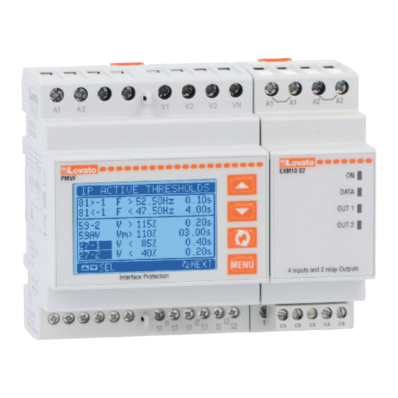
Page 3: Displaying Measurements
– The thresholds used during IP operation and the corresponding delays are displayed in a dedicated video page: FRONT BUTTON FUNCTIONS MENU button - Used to enter or exit the various display and setup menus. Buttons s and t - Used to scroll between screens, select from available options on the display and change (increase/decrease) settings. Button ✔... - Page 4 – The user can specify the page and sub-page to return to automatically after no buttons have been pressed for a given time. – It is also possible to program PMVF 80 so that the display always remains that which was last selected.
-
Page 5: Password-Protected Access
MAIN MENU – The main menu consists of a set of graphic icons which allow rapid access to measurements and settings. – Starting from the normal measurement display, press the MENU button. The display shows the quick menu (see figure below). –... - Page 6 P01.07 – Rated active power of system. If set to AUT, the value is calculated by multiplying P01.04 * “rated VLN” * 3 (phase current * phase voltage * 3 phases). P01.08 – IS energising delay time after applying voltage to PMVF 80.
- Page 7 P01.12-13 – Second-level LSP (LSP2) threshold and delay. P01.14 – Defines the automatic restore time after LSP tripping. If set to off, the system can only be restored manually by pressing the s t buttons. P01.15 – Defines the function of the OUT4 output from those listed. The output is understood to be activated when conditions are normal (threshold not exceeded, alarm not active, etc.). P01.16 –...
- Page 8 M05 – COMMUNICATION Default Range P05.1.01 Serial node address 01-255 P05.1.02 Serial speed 9600 1200 2400 4800 9600 19200 38400 P05.1.03 Data format 8 bit – n 8 bit, no parity 8 bit,odd 8 bit, even 7 bit, odd 7 bit, even P05.1.04 Stop bits P05.1.05 Protocol Modbus-RTU...
- Page 9 SELF-DIAGNOSIS – The PMVF 80 features a series of self-diagnosis checks. If any of these checks is unsuccessful, a window displaying the text System Error Exx is displayed, where xx indicates the reason for malfunction. Should this indication occur, contact our Technical Support office (Tel. + 39 035 4282422; E-mail: service@LovatoElectric.com), stating the code indicated.
- Page 10 – It is possible to restore manually by pressing the s t, buttons simultaneously, or automatically by waiting for the time set with P01.14. COMMUNICATION – The PMVF 80 can be fitted with an optional standard communication module from those listed below. When a communication module is installed, it must be configured through the dedicated M05 - COMMUNICATION MENU.
- Page 11 BACKUP ACTIVATION MODES Note: the default backup control mode is A. If mode D is selected, Backup output mirrors the IS output. See parameter P01.16 (M01 - GENERAL MENU on page 6). TERMINAL LAYOUT MECHANICAL DIMENSIONS [MM] MOUNTING INSTRUCTION DEMOUNTING INSTRUCTION DEVICE SYMBOLS Warning: read the present instruction manual...
-
Page 12: Technical Characteristics
TECHNICAL CHARACTERISTICS Auxiliary supply Digital inputs Rated voltage Us 100 - 240V~ Number of inputs 110 - 250V= Input type Positive (PNP) Operating range 85 - 264V~ Voltage present on inputs 12V= isolated 93.5 - 300V= Input current Frequency 45 - 55Hz Low input signal (ON) 1.5V (2.9V typical) ≥5.3V (4.3V typical)
Need help?
Do you have a question about the PMVF 80 and is the answer not in the manual?
Questions and answers