
Related Manuals for ETAS CBS100.1-2

Summary of Contents for ETAS CBS100.1-2
- Page 1 CBS100.1-2 / CBS104.1-2 / CBS105.1-2 Smart Lambda Sensor Cable User‘s Guide www.etas.com...
- Page 2 The data in this document may not be altered or amended without special noti- fication from ETAS GmbH. ETAS GmbH undertakes no further obligation in relation to this document. The software described in it can only be used if the customer is in possession of a general license agreement or single license.
-
Page 3: Table Of Contents
ETAS Contents Contents General ............. . 5 About this Manual . - Page 4 ETAS Contact Addresses ........
-
Page 5: General
ETAS General General This chapter contains information about the following topics: • “About this Manual” on page 5 • “Basic Safety Notices” on page 6 • “Identifications on the Product” on page 9 • “RoHS Conformity” on page 10 •... -
Page 6: Basic Safety Notices
Carefully read the documentation that belongs to the product prior to the startup. ETAS GmbH does not assume any liability for damages resulting from improper handling, unintended use or non-observance of the safety precau- tions. -
Page 7: Requirements For Users And Duties For Operators
ETAS General 1.2.3 Requirements for Users and Duties for Operators The product may be assembled, operated and maintained only if you have the necessary qualification and experience for this product. Improper use or use by a user without sufficient qualification can lead to damages or injuries to one's health or damages to property. - Page 8 ETAS General Fastening with cable ties CAUTION Damage to the housing is possible! Cable ties for fastening the Smart Lambda Sensor Cable may be attached only to the infeed lines of the cable. Fastening on the electronic module (housing) of the cable is not allowed.
-
Page 9: Identifications On The Product
Reference shall be made to the use of the software in order to fulfill OSS licensing terms. Additional information is available in the document "OSS Attri- butions List" at the ETAS website www.etas.com. Identifications on the Product The following symbols are used for identifying the product:... -
Page 10: Rohs Conformity
The user is obligated to separately collect old devices and provide them to the WEEE return system for recycling. The WEEE Directive applies to all ETAS devices, but not to external cables or batteries. Additional information about the recycling program of ETAS GmbH is available from the ETAS sales and service locations (see chapter 6 on page 37). -
Page 11: Hardware Description
Overview 2.1.1 Products and Application Areas The Smart Lambda Sensor Cables CBS100.1-2, CBS104.1-2 and CBS105.1-2 convert the signal of a Bosch LSU4.9 broadband lambda sensor into an analog output signal. The three Smart Lambda Sensor Cables of this product family were developed for different applications. -
Page 12: Properties
Hardware Description CBS100.1-2 and CBS105.1-2 If the Smart Lambda Sensor Cables CBS100.1-2 and CBS105.1-2 are supplied with DC voltage, it can be configured whether the output signal is a function either of the oxygen content or the lambda value of the gas or the pump current of the sensor. -
Page 13: Design Of The Smart Lambda Sensor Cable
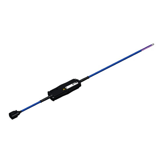
ETAS Hardware Description Design of the Smart Lambda Sensor Cable Fig. 2-2 Design of the Smart Lambda Sensor Cable Part in Comment Fig. 2-2 RB150 coupling (code 1) for the Bosch LSU4.9 lambda sen- Electronic module with measurement electronics and heater... -
Page 14: Inputs And Outputs (Open Cable End)
27. 2.2.4 Connections "AOUT" and "AOUT_GND" CBS100.1-2 and CBS104.1-2 The "AOUT" connection of the Smart Lambda Sensor Cables CBS100.1-2 and CBS104.1-2 is a voltage output. CBS105.1-2 The "AOUT" connection of the CBS105.1-2 Smart Lambda Sensor Cable is a passive current output (4 to 20 mA). -
Page 15: Fig
Output signals and measure variables Supply with DC voltage If the Smart Lambda Sensor Cables CBS100.1-2 and CBS105.1-2 are supplied with DC voltage, the wiring of the "CONFIG" connection allows selecting to which measure variable the signal issued at the "AOUT" connection is assigned (see chapter 4.3.4 on page 29). -
Page 16: Config" Connection (Configuration Input)
Hardware Description Supply with AC voltage If the Smart Lambda Sensor Cables CBS100.1-2 or CBS105.1-2 are supplied with AC voltage, the oxygen content is issued as measure variable at the "AOUT" connection. The measure variables lambda and pump current cannot be selected in the operating mode. -
Page 17: Connections "Ac1" And "Ac2" (Voltage Supply)
ETAS Hardware Description Contrary to the industry standard (current interface 4 to 20 mA), the CBS105.1-2 Smart Lambda Sensor Cable does not supply an increased cur- rent signal at the "AOUT" output in case of an error. An error case is signaled at the "ERROR"... -
Page 18: Commissioning
ETAS Commissioning Commissioning This chapter contains information about the following topics: • “General Recommendations for Installation and Operation” on page 18 • “Startup Sequence” on page 19 • “Assembly of the Lambda Sensor” on page 19 • “Cabling” on page 22... -
Page 19: Lambda Sensor
ETAS Commissioning 3.1.2 Lambda Sensor With improper handling, the lambda sensor can deteriorate prematurely or be damaged. Deteriorated or defective lambda sensors Deteriorated or defective lambda sensors must be replaced with a new unit. De- energize the Smart Lambda Sensor Cable before replacing the lambda sensor. -
Page 20: Notes About Installing The Lambda Sensor
ETAS Commissioning 3.3.2 Notes about Installing the Lambda Sensor The following general guidelines should be taken into consideration when installing the LSU lambda sensor: • Select the installation location in exhaust-gas lines so that a representa- tive exhaust gas composition is ensured while maintaining the specified temperature limits. -
Page 21: Assembly Of The Bosch Lambda Sensor
ETAS Commissioning 3.3.3 Assembly of the Bosch Lambda Sensor Assembling the LSU4.9 lambda sensor During the assembly of the lambda sensor, observe the installation guidelines in chapter 3.3 on page 19. 1. Select a position for the lambda sensor that is not too close to the combustion chamber to avoid a possible overheating of the sensor and heat damages to the sensor. -
Page 22: Cabling
ETAS Commissioning Cabling The connections of the CBS10x.1-2 Smart Lambda Sensor Cable can be cabled in any order. The "CONFIG" connection of the CBS104.1-2 Smart Lambda Sensor Cable is without function. When supplying the CBS10x.1-2 Smart Lambda Sensor Cables with AC volt- age, the connections "CONFIG"... -
Page 23: Config" Connection (Configuration Input)
ETAS Commissioning 3.4.3 "CONFIG" Connection (Configuration Input) The measure variable output at the "AOUT" output can be selected by wiring the "CONFIG" connection. Please observe the information in chapter 2.2.4 on page 14 and in chapter 2.2.5 on page 16. -
Page 24: Connections "Ac1" And "Ac2" (Voltage Supply)
ETAS Commissioning 3.4.5 Connections "AC1" and "AC2" (Voltage Supply) The measurement electronics in the CBS10x.1-2 Smart Lambda Sensor Cable and the heater of the lambda sensor are connected with the power sup- ply at a common connection (AC1). Requirements on the voltage supply of the Smart Lambda Sensor Cable are located in the chapter 4.3.1 on page 28. -
Page 25: Technical Data
ETAS Technical Data Technical Data This chapter contains information about the following topics: • “General Data” on page 25 • “Mechanical Data” on page 26 • “Electrical Data” on page 28 General Data 4.1.1 Standards The product meets the following standards:... -
Page 26: Mechanical Data
ETAS Technical Data Mechanical Data 4.2.1 Dimensions and Weight Fig. 4-1 Dimensions of the Smart Lambda Sensor Cable Cable length (overall) 2 m / 78.75 in Cable length A (line from electronic 1.7 m / 66.93 in module including open cable end) Dimensions of electronic module 21.6 mm x 126.4 mm x 50 mm... -
Page 27: Lambda" Connection With Rb150 Coupling (Part 1 In Fig. 4-2)
ETAS Technical Data 4.2.3 "LAMBDA" Connection with RB150 Coupling (part 1 in Fig. 4-2) Fig. 4-3 RB150 Sensor Coupling (Code 1) On pin Color Signal Action White Pump current Green Virtual ground Black Heater minus Heater plus Pink Trimming resistance... -
Page 28: Electrical Data
ETAS Technical Data Electrical Data 4.3.1 Voltage Supply Operating voltage 10 V to 14 V DC and 10 V to 13 V AC, 60 Hz ±1 Hz Heater supply PWM with approx. 100 Hz Current consumption (typ.) 1.1 A at 12 V DC Current consumption (max.) -
Page 29: Lambda" Connection With Rb150 Coupling
The "CONFIG" configuration input is at the potential of the supply voltage and not at the potential of the output signal. When supplying the Smart Lambda Sensor Cables CBS100.1-2 or CBS105.1- 2 with AC voltage, the connections "CONFIG" and "ERROR" are without func- tion. -
Page 30: Error Output ("Error" Connection)
When supplying the CBS10x.1-2 Smart Lambda Sensor Cables with AC volt- age, the connections "CONFIG" and "ERROR" are without function. 4.3.6 "AOUT" Connection ("AOUT" Analog Output) 4.3.6.1 CBS100.1-2: Properties and ratings Output voltage 0 V to 10 V Output current -5 mA to +5 mA Output impedance typ. - Page 31 ETAS Technical Data 4.3.6.2 CBS104.1-2: Properties and ratings Output voltage -20 mV to +80 mV; LSM11 emulation Output impedance typ. 100 ohm Protection against short circuit, max. external voltage -0.3 V to +3 V Electrical isolation max. 60 V DC (output to supply volt- age) The output is high-impedance in de-energized state.
-
Page 32: Cbs100.1-2: Measure Ranges And Graduation
ETAS Technical Data 4.3.7 CBS100.1-2: Measure Ranges and Graduation 4.3.7.1 Lambda measure variable sçìí=xsz i~ãÄÇ~ Measure vari- Measure range Graduation able Lambda 0.65 to 5.0 = 2.0 V * The values listed for measure range and graduation apply to new lambda sen- sors at 1013 hPa. -
Page 33: Cbs104.1-2: Measure Range And Graduation
ETAS Technical Data 4.3.7.3 Pump current measure variable sçìí=xsz fé=xã^z Measure vari- Measure range Graduation able Pump current I -2.5 mA to +2.5 mA = 5.0 V + 2.0 V * I [mA] 4.3.8 CBS104.1-2: Measure Range and Graduation Together with an LSU4.9 lambda sensor, the CBS104.1-2 Smart Lambda Sen- sor Cable emulates an LSM11 discrete-level sensor. -
Page 34: Cbs105.1-2: Measure Ranges And Graduation
ETAS Technical Data 4.3.9 CBS105.1-2: Measure Ranges and Graduation 4.3.9.1 Lambda measure variable fçìí=xã^z i~ãÄÇ~ Measure vari- Measure range Graduation able Lambda 0.65 to 5.0 = 4 mA + 3.2 mA * The values listed for measure range and graduation apply to new lambda sen- sors at 1013 hPa. - Page 35 ETAS Technical Data 4.3.9.3 Pump current measure variable: Measure range and graduation fçìí=xã^z fé=xã^z Measure vari- Measure range Graduation able Pump current I -2.5 mA to +2.5 mA = 12 mA + 3.2 mA * I [mA] CBS10x.1-2 - User’s Guide...
-
Page 36: Ordering Information
Ordering Information Ordering Information Order name Short name Order number CBS10x.1-2 Smart Lambda Sensor Cable CBS100.1-2 F 00K 107 904 for Bosch LSU4.9, Universal, Voltage Out- put, RB150, open wire, 2 m CBS104.1-2 Smart Lambda Sensor Cable CBS104.1-2 F 00K 107 906 for Bosch LSU4.9, LSM11 Emulation Out-... -
Page 37: Etas Contact Addresses
Germany Internet: www.etas.com ETAS Subsidiaries and Technical Support For details of your local sales office as well as your local technical support team and product hotlines, take a look at the ETAS website: ETAS subsidiaries Internet: www.etas.com/en/contact.php ETAS technical support Internet: www.etas.com/en/hotlines.php... -
Page 38: Figures
ETAS Figures Figures Fig. 1-1 WEEE Symbol ............10 Fig. -
Page 39: Index
Voltage supply ..... .28 ETAS Contact Addresses ... . .37 Waste Electrical and Electronic Equipment Heat-up characteristics .
Need help?
Do you have a question about the CBS100.1-2 and is the answer not in the manual?
Questions and answers