Table of Contents
Advertisement
Quick Links
Advertisement
Table of Contents

Related Manuals for ITALMOTO Clodia

Summary of Contents for ITALMOTO Clodia
- Page 1 OWNER’S MANUAL...
- Page 2 INFORMATION Before taking your first ride, read this Owner’s Manual carefully and familiarise yourself with your ITALMOTO e-bike. For your own safety and a longer service life for your e-bike, follow the instructions and warning notices in this manual. Disregarding them may lead to damage to the e-bike or personal injury.
- Page 3 All information in this publication is based on the latest production information available at the time of approval for printing. The manufacturer reserves the right to make changes at any time without notice and without incurring any obligation. No part of this publication may be reproduced without written permission.
-
Page 4: Dear Customer
DEAR CUSTOMER: Thank you for purchasing this ITALMOTO e-bike. This e-bike is a product manufactured by using advanced equipment and made up of high-quality component parts. This manual provides detailed information about correct operation, maintenance and adjustment of your e-bike. By following these tips your unit will be more durable. -
Page 5: Product Information
Despite ongoing market research, ITALMOTO is unable to assess other parts. Therefore, ITALMOTO accepts no responsibility for the use of such parts in ITALMOTO e-bikes. This is also the case, even if they have been independently or officially approved. The use of non-approved parts could affect the safety of your e-bike. - Page 6 Should you have any life for your e-bike, follow the instructions questions concerning equipment and ope- and warning notices in this manual. Disre- ration, please consult a ITALMOTO garding them may lead to damage to the dealer. e-bike or personal injury.
- Page 7 OPERATING SAFETY N WARNING When being used, the mechanical com- Important safety notes ponents of the e-bike are subjected to high N WARNING loads and wear. Components react diffe- Components can be damaged without it rently to these loads and show signs of being visible on the surface: fatigue or wear at different rates.
- Page 8 • Handlebars and stem carried out at a qualified specialist wor- • Saddle and seat post kshop. • Frame and fork Do not make any modifications or carry • Tires and wheels out work, such as drilling, soldering or • Pedals and pedal cranks welding, on the frame or other load-be- •...
- Page 9 • work on the drive system ghting system will not function. Riding ITALMOTO recommends that you use a without an operational lighting system is ITALMOTO dealer which is qualified to not permitted, depending on national re- carry out work on ITALMOTO e-bikes.
- Page 10 The configuration of your ITALMOTO The ITALMOTO e-bike is designed to be e-bike can vary, depending on the ridden on asphalt roads and lanes as well country in which you purchased it. Using as surfaced forest and country tracks. The...
- Page 11 ITALMOTO e-bike is used for the smartphone and net pockets. purposes it was designed for. If the ITALMOTO e-bike is used in ways for which it was not designed, this could result in damage to the fitted components. This could then lead to accidents and injuries.
- Page 12 E-BIKE...
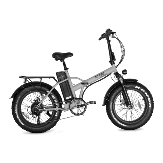
- Page 13 The Clodia frame, as illustrated, can be folded and houses the battery. A quick lock system permits fast folding to reduce size for easier Clodia transport.
- Page 14 Near the two parts of the frame as illustrated. Match up the two parts. Make sure that the fastening lever is locked in his close position. Proceed in reverse order to open the frame and fold the Clodia.
- Page 15 The Clodia comes with the stem lowered First, lift it to the vertical position...
- Page 16 Close the lock lever pushing upwards Rotate the safety ring to prevent the fastening lever from accidentally unlocking. Proceed in reverse order to fold up the Clodia.
- Page 17 Insert the sleeve of the saddle in its housing and adjust the height and tilt, by turning the screws and quick-release terminals, as shown in the figure. The pedals will arrive disassembled and in a separate plastic bag. Carefully screw the pedals into the dedicated seat and tighten with the spanner supplied.
- Page 18 INSPECTION BEFORE STARTING The ITALMOTO e-bike is equipped with a li-ghting system with the active and A JOURNEY passive components required for use on public ro-ads. It also has an appropriate Useful information brake sy-stem and a bell. This Owner’s Manual describes all mo-...
- Page 19 Wear conspicuous, bright clothing appro- priate for cycling and shoes which are su- itable for the bike’s pedals. When riding in traffic, always be considerate and obser- ve the traffic rules and regulations in order to avoid endangering yourself and others.
- Page 20 INSPECTION BEFORE STARTING • tire tread depth • true running of the wheels by allowing A JOURNEY both wheels to rotate freely. Out-o- fround wheels can be an indication Checking tires and wheels of tires which have burst at the side, N WARNING broken axles or torn spokes.
- Page 21 tensioned, and the transmissions Checking the operation of the brake gears are bolted securely. system • Also check for proper installation of Before every ride, carry out a stationary the slip guard to prevent the chain brake test. To do so, pull the brake levers jumping teeth or slipping.
- Page 22 Check the brake pads for wear before pushing and pulling on the rear wheel every ride. must not cause it to move. Carry out a visual inspection of the brake • check to make sure the handles and discs: brake handles are securely seated. It •...
- Page 23 The length of the seat post The optimum seat position is an important can be adjusted to your individual body factor for your well-being on the size. Further details can be obtained ITALMOTO e-bike. A comfortable and from any ITALMOTO Centre. fatigue-free...
- Page 24 ADJUSTING THE SADDLE Adjusting the saddle height N WARNING If you pull the seat post too far out of the seat tube, then the clamp can no longer secure the seat post sufficiently. The seat post could come loose or break during the tour.
- Page 25 The wrist should be as straight as possible when doing so. Pedals The pedals on your ITALMOTO e-bike are suitable for closed shoes with hard soles. Touring cycling shoes which are equally suitable for cycling and walking...
-
Page 26: Driving Tips
Country-specific differences are possible. Note that your e-bike may not be fitted The ITALMOTO e-bike only assists you with all features described. This is also when you apply force to the pedals. the case for systems and functions rele- When you stop pedalling, the electric vant to safety. - Page 27 • to charge the battery during the tour, The range of the ITALMOTO e-bike use generator mode as often as pos- with a fully charged battery depends sible. on the following factors: •...
- Page 28 • water between the brake pads and The ITALMOTO e-bike is equipped with brake disks reduces the effect of the brakes which will bring you to a standstill brake system. quickly and safely, if required. Disc The braking distance is increased. There brakes respond more quickly than rim is a risk of an accident.
- Page 29 again. Stop at the first signs of overhea- ting. Symptoms indicating overheating include: • Rincreased hand strength • The build up of smelling • Loud scraping noises Let the brake system cool down before riding on. Wet conditions reduce the braking effect and lead to the tires skidding more easily.
- Page 30 • Only use the battery for the ITALMOTO bike. N WARNING • Do not expose the battery to storage Using a charger other than the one sup-...
- Page 31 above 45°C (113°F). Please note that strong smell, alters in appearance or temperatures above 45 °C (113°F) can behaves abnormally in any way, stop occur around heaters, in direct sunli- using the battery immediately. ght or in overheated vehicle interiors. •...
- Page 32 tage range of 240 V. The charger has no mory effect. on/off switch. If you do not require the • brief discharges with subsequent charger, disconnect the plug to save charges can cause an inconsistency energy. between the charge indicator and the battery charge level.
- Page 33 Connecting the charger The battery (1) can be charged either on the bike or can be removed and charged separately.When the battery is charged on the bike, the system can be switched on or off du-ring charging. Connect the charger to charging port on battery (2).Connect the charger’s mains plug to a socket.
-
Page 34: Removing/Fitting The Battery
REMOVING/FITTING THE BATTERY Insert the battery in its housing as shown in the figure, helped by its rail. Once the battery is placed, lock it with the key (position OFF). To use the e- bike you must place the key on "ON" position. - Page 35 Storing the battery (113°F). N WARNING • do not expose the battery to tempe- Deep battery discharge can cause an in- rature fluctuations. The ideal storage ternal short circuit. The battery heats up temperature is between 10°C (50°F) to an extremely high temperature. There and 25°C (77°F).
- Page 36 • turning it inside out For this reason, you should regularly in- • reverse bending spect the tension of the spokes and have • tying or binding it up with cable ties or them re-centred by a ITALMOTO dealer.
- Page 37 Check the tire pressure regularly, at least pump with a manometer. As your every 14 days. Only correct tire pressu- ITALMOTO e-bike’s tires are fitted with res when the tires are cold. The pressure robust puncture protection made from of warm tires should only be corrected if...
-
Page 38: Maintenance And Care
The best protection from harmful environmental influences is regular cleaning and preservation. ITALMOTO recommends performing a paint treatment twice a year (e.g. in spring and autumn). • Use as little water as possible and keep water away from electrical con- tacts. -
Page 39: Maintenance
MAINTENANCE Regular work ITALMOTO recommends that you have the e-bike serviced once a year at a qualified specialist workshop. Before each journey • Check tires and wheels • Check the chain • Check the battery lock • Inspect the functioning of the brake system •... - Page 40 Every 3000 km (1864 miles) Check the following components and replace, if necessary: • headset • wheel hubs • pedals • chain • gear cable Once a year • Check torques of all screw and bolt connections. • Check gearshift, headset and brake settings •...
-
Page 41: Troubleshooting
TROUBLESHOOTING Control console Problem Possible causes/consequences and Solutions system will The battery is low or discharged. switch display Check the charge level directly on the battery, charge remains dark. if necessary. The battery is not positioned correctly in the holder. Remove the battery and then reinstall If the problem persists despite taking these measures: Have the electrical system checked at a qualified spe-... - Page 42 Lighting system Problem Possible causes/consequences and Solutions The lighting system is not The battery is low or discharged. working. Check the charge level directly on the battery, charge if necessary. The electrical connectors have come loose. Check the electrical connectors. If the problem persists despite taking these measures: Have the electrical system checked at a qualified spe- cialist workshop.
- Page 43 Battery Problem Possible causes/consequences and Solutions The charge indicator on The battery has been affected by the ambient tempe- the control console is not rature. The battery heats up during the charging pro- showing that the battery is cedure. “full” even though a full bat- Let the battery cool down and repeat the charging pro- tery charge has been perfor- cess.
- Page 44 Drive system/electric motor Problem Possible causes/consequences and Solutions The system can be switched The electrical connections on the handlebars or near on but the electric motor the motor are not inserted correctly or have become does not provide any assi- detached.
- Page 45 Brake system Problem Possible causes/consequences and Solutions Poor braking performance. The brake was not bedded in. Bed in the brake The brake discs or brake pads are fouled with oil. • Clean the brake discs with alcohol. • Replace the brake pads. •...
- Page 46 Problem Possible causes/consequences and Solutions Poor braking performance, Air in the braking system. no defined actuation point. Have the brake system bled at a qualified specialist workshop. The brake is making grinding There is dirt or water on the brake disc or brake pads. noises during the journey.
- Page 47 Problem Possible causes/consequences and Solutions The brake squeaks when The brake calliper is not exactly aligned with the brake applied. disc. Have the brake calliper correctly aligned in a qualified specialist workshop. There is insufficient tension in the spokes of the wheel. Have the tension of the spokes checked and corrected at a qualified specialist workshop.
- Page 48 Shifting gear Problem Possible causes/consequences and Solutions It is not possible to engage There is too much tension in the gear cable. a gear. Reduce the tension of the gear cable at the twist-grip If the problem persists despite taking these measures: Have the gear shifting system checked at a qualified specialist workshop.
- Page 49 TECHNICAL DATA BIKE Max power 250 W Max speed 25 Km/h Speed level Electric motor Rear Hub Battery Features 36V – 10.4 Ah Iithium ions Autonomy 50 Km Charging time Lifetime 800 cicles Display LCD Controlo Panel...
-
Page 50: Technical Data
TECHNICAL DATA Aluminium alloy Body 20’’ tires Disc brakes Brakes Aluminium, hydraulic Fork Shimano 7 speed Gear and Trasmission... - Page 51 The unladen weight given is for the stan- type and size with a suitable tread. If in dard scope of delivery. Accessories and doubt, contact your nearest ITALMOTO items of optional equipment increase the dealer. The reflective strips on the tire...
- Page 52 LCD CONTROL DISPLAY 1. . 1.77'' inch, 160x128 color TFT LCD scre 4. . "+" butt 2. . USB port with protective cov 5. . "i" display function butt 3. . Mounting brack 6. . "-" butt • Technical Parameter Rated operating voltage 24V /3 6V /48 V DC USB port output...
-
Page 53: Instrument Interface
Instrument interface • Instrument interface is the default interface on the instrument Status Bar Motor output energy Riding speed Information display area Speed stage Headlight status Lithium battery capacity Time Data indicator... - Page 54 • Key function "+" key Short press once Long press for 3 seconds Press and hold for a long time Instrument functions Increased power Headlight on/off ---- Menu interface Cursor up/increase ---- ---- "-" key Short press once Long press for 3 seconds Press and hold for a long time Instrument functions Decreased power...
- Page 55 "i" key Short press once Long press for 3 seconds Press and hold for a long time Change information Instrument system On/Off Instrument functions display Menu interface ---- ---- OK/Confirm 4. . & Press both keys simultaneously Short press once Long press for 3 seconds Press and hold for a long time Instrument functions...
-
Page 56: Information Display Area
Information Display Area In the instrument interface, short press the "i" key for circulation browsing of the information of various riding and electric bicycles. Mileage Total mileage Maximum driving speed Average speed Real-time motor output power Today's riding time Today's calories burned... - Page 57 * If the electric bicycle is not ridden, the riding time statistics will be suspende and reset to zero at 00:00 every day. * Calories and riding time statistics are reset to zero at 00:00 every day System configuration precautions Changing the parameters in the "System Configuration"...
-
Page 58: System Operation
System Operation • Initial operation Set the system time 1. . Press the "+" and "-" two keys simultaneously and hold for 2 seconds to enter the main me page of the system 2. . Press the "+" key and select the "Display Setting" field, and then press "i" to confi 3. -
Page 59: Other Interfaces
Other Interfaces • Error code notification List of error codes (example only, depending on customer) Error code Corresponding error conditions Solutions to corresponding errors Check if the three-phase power line is connected Controller protection properly Check accelerator conductor connections and Accelerator error replace motor if necessary Check motor conductor connections and replace... - Page 60 Further information about ITALMOTO vehicles can be found on the following website: http://www.italmoto.com ITALMOTO reserves the right to make changes and improvements to any of the products described in this document without prior notice.
- Page 62 Motocicli Italiani S.r.l. - Italy...
Need help?
Do you have a question about the Clodia and is the answer not in the manual?
Questions and answers