
Related Manuals for Seg SP740 Series


Summary of Contents for Seg SP740 Series
- Page 1 INSTRUCTION MANUAL SMART POSITIONER SP740 Series Shin Hwa Eng Co., Ltd Software ver. : SP-4MIS V1.1 Manual ver. : SA-6-10/2019 1/40 1/40...
-
Page 2: Table Of Contents
Smart Positioner SP740 Series TABLE OF CONTENTS 1. Introduction .--------------------------------------------------------------------------------------------------------------------------------- .-------------------------------------------------------------------------------------------- General Information for users . .---------------------------------------------------------------------------------------------------- Caution on safety -------------------------------------------------- Basic safety instruction for using in the Explosion proof area. --------------------------------------------------------------- Conditions to maintain the Intrinsic Safety (EXi) .--------------------------------------------------------------------------------------- Certification .---------------------------------------------------------------------------------------... - Page 3 Smart Positioner SP740 Series .--------------------------------------------------------------------------------------- 5. Connection - Power .--------------------------------------------------------------------------------------- Safety .--------------------------------------------------------------------------------------- Termainal Connection .--------------------------------------------------------------------------------------- Limit Switch Terminal Instrinsic safety's parts terminal Connection ------------------------------------------------------------------------------- .--------------------------------------------------------------------------------------- Ground .--------------------------------------------------------------------------------------- 6. Adjustments .--------------------------------------------------------------------------------------- Limit Switch Adjustment .--------------------------------------------------------------------------------------- 7. PCB board Type --Option .-------------------------------------------------------------------------------------------- 8.
-
Page 4: Introduction
☞ The manual should be provided to the actual end-user. ☞ SP740 Series hardware and software version may be upgraded without prior notice. ☞ For additional information or if there occur problems that are not stimulated on this manual, Please contact to Shinhwa Eng Co., Ltd. Immediately. -
Page 5: Basic Safety Instruction For Using In The Explosion Proof Area
Smart Positioner SP740 Series 1.3 Basic safety instruction for using in explosion proof area To prevent the the risk of explosion , it is necessary to install the product according to the basic safety instruction to operate in Exi area and national or the regional explosion proof regulations and to prepare proper safety barrier when organizing the system. -
Page 6: Product Description
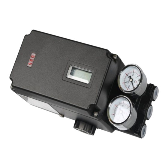
2. Product Description General Introduction Smart Positioner SP740 series are I/P converter type positioner operating kinds of actuators and valves by converting 4 to 20mA DC signal to pneumatic output proportionally. The product has acquired IECEx certificate according to "IEC60079-0:2011, IEC60079-11:2011"... -
Page 7: Label Description
Smart Positioner SP740 Series 2.4 Label Description Fig.2-1: SP740 Non-Explosion Proof sticker label Fig. 2-2: SP740 Intrinsic safety explosion proof sticker label Items of label Description Model No. Indicate model number according to model & specification Instrinsic safety / Non-... -
Page 8: Products Code
Smart Positioner SP740 Series Products code SP740 / S : Single Acting type D : Double Lever Type L1 : 20 ~ 80 mm Linear L2 : 80 ~ 160 mm R0 : Standard Rotary R1 : Fork lever R2 : Namur... -
Page 9: Products Specification
Smart Positioner SP740 Series Products Specification Model SP740S SP740D Acting Type Single Double Linear Rotary Linear Rotary Motion type Input Signal 4 ~ 20mA DC Minimum Current Signal 2.8mA(Standard), 3.8mA (HART Included) Impedance Max. 450Ω @ 20mA DC Air Connection... -
Page 10: Principle Of Operation
Smart Positioner SP740 Series 2.7 Principle of Operation Once Control PCB(3) receives an input signal(4~20mA), the input current is delivered to coil(6) of Torque Motor(1), from which magnetic force is generated in core(7) and the force and polarity difference with a permanent magnet moves nozzle flapper(9), by which nozzle(8)and nozzle flapper (9) are far isolated, lowering the pressure of nozzle pressure chamber and finally generating the difference of pressure with the pressure chamber(14). -
Page 11: Explosion Proof Specifications Of Intrinsic Safety
Smart Positioner SP740 Series Explosion proof specifications of Intrinsic Safety IEC 60079-0:2011 Intrinsic Safety Explosion proof regulations IEC 60079-11:2011 Intrinsic safety explosion proof Ex ia ⅡC T5/T6 grade Barrier specifications Main power 93mA 651mW 35uH Feedback signal power 93mA 651mW... -
Page 12: Structure
Smart Positioner SP740 Series Structure SP740 Series Schematic View ①COVER ⑥Potention meter ② PCB Cover ⑦Pilot ③Control PCB ⑧Pilot Valve ④Torque Motor ⑨Base Body ⑤ Main Shaft ⑩Cage Block Fig 2-4 Schematic View 12/40 12/40... -
Page 13: Products Dimension
Smart Positioner SP740 Series 2.10 Products Dimension 2.10.1 SP740 Standard Type Fig 2-5 : SP740 Standard Type 13/40 13/40... -
Page 14: Sp740 Lever Type
Smart Positioner SP740 Series 2.10.2 SP740 Lever Type Fig 2-6 : SP740 Lever Type 14/40 14/40... -
Page 15: Sp740 Fork Lever Type
Smart Positioner SP740 Series 2.10.3 SP740 Fork Lever Type Fig 2-7 : SP740 Fork Lever Type 15/40 15/40... -
Page 16: Sp740 Namur Type
Smart Positioner SP740 Series 2.10.4 SP740 Namur Type Fig 2-8 : SP740 Namur Type 16/40 16/40... -
Page 17: Installation
Smart Positioner SP740 Series 3. Installation Caution before Installation Warning ☞ Maintain proper air pressure and prevent to insert alien substrance and install filter regulator in Positioner inside air supply line . ☞ Supplying air should not be mixed with oil, moisture and impurities. - Page 18 Smart Positioner SP740 Series 3.3.2 Standard Lever Type Positioner installation ① ① Feedback lever ⑤ ② Spacer ③ Bracket ② ④ Bolt(M8) ③ ⑤ Connection bar ④ Figure 3-2: SP740 Standard lever type ① Assemble with the enclosed bracket and bolts.
- Page 19 Smart Positioner SP740 Series Figure 3-3 SP740 (standard lever type) ④ Connection bar located on actuator clamp should be inserted into spring in positioner feed back lever hole as seen as figure. hole as seen as figure. Figure 3-4 Insert connection bar between lever and lever spring correctly.
- Page 20 Smart Positioner SP740 Series ⓐ Check a valve's full stroke. ⓑ Connection bar should be consisted with feed back lever's value and full stroke value's equal point . ⓒ If positioner lever and actuator connection bar has not consistent , move and adjust positioner bracket or connection bar.
-
Page 21: Rotary Positioner Installation
Smart Positioner SP740 Series 3.4 Rotary positioner Installation Rotary positioner is used for 90 ˚ rotating valve. There are fork lever type and namur type ⑥ NAMUR TYPE ⑤ Fig3-6 Fig 3-7 SP740 Fork lever type SP740 Namur type 3.4.1 Bracket Set assembly for Rotary Positioner Installation ①... -
Page 22: Rotary Positioner Installation Step
Smart Positioner SP740 Series 3.4.2 Rotary Positioner Installation Step ① Connect upper/lower bracket assemblies onto an actutor with bolts. Note the positioner manufacturer does not supply bolts to fix an actuator. Actuator Lower/upper bracket Clockwise / counterclockwise ② With an actuator's initial start point of 0%, install the fork lever as seen in figure according to the rotation direction of stem. -
Page 23: Connection - Air
Smart Positioner SP740 Series 4. Connection - Air 4.1 Supply Pressure Conditions Caution ☞ Make sure that air filter regulator should be installed on the front of positioner. ☞ Supplying air should not be mixed with oil, moisture or impurities. -
Page 24: Connection - Power
Smart Positioner SP740 Series 5. Connection - Power 5.1 Safety Warning ☞ Please check whether power is disconnected before connecting terminals. ☞ Supply the lower than described currenct and votlage ☞ Do not install cable on near equipments incurred by noise such as high capacity transformer or motor. -
Page 25: Instrinsic Safety's Parts Terminal Connection
Smart Positioner SP740 Series 5.4 Instrinsic safety's parts terminal Connection ☞ Make sure that instrinsic safety wire must be separated with general wire. ☞ Make sure that electrical parameter must be maintained lower than values indicated on explosion proof certificate. -
Page 26: Adjustments
Smart Positioner SP740 Series 6. Adjustments 6.1 Limit Switch Adjustment To adjust the operation location of a limit switch, looseen the CAM fixed screw, rotate it to a desirable position and tighten screw again. CAM rotor 회전자 Fig : 6-1... -
Page 27: Pcb Board Type --Option
Smart Positioner SP740 Series 7. PCB board Type - Option Position transmitter(PTM) and HART communication can be easily mounted as added function. There are four type PCB as followings. Fig 7-1 : Standard PCB board Fig 7-2 : Standard PCB board + limit switch type <... -
Page 28: Auto Calibration & Pcb Operation
Smart Positioner SP740 Series 8. Auto Calibration & PCB Operation 8.1 Warning Warning Before working auto calibration , make sure that they have not influence on overal process after saparating valve and actuator in system completely. 8.2 Button Description The positioner has four(4) buttons. -
Page 29: Auto Calibration Mode (Auto Cal)
Smart Positioner SP740 Series 8.4 Auto Calibration Mode (AUTO CAL) In case of using AUTO CAL function , control position and function necessary in adjustment can be set automatically. 5-10 minutes are required and according to driving size, the requiring time can increased or decreased. -
Page 30: Manual Mode ( Manual )
Smart Positioner SP740 Series 8.5 Manual Mode ( MANUAL ) Manual mode is a mode to check if there is no mechanical interference and problem when installing the positioner and valve in the first time. Press the <UP> and <DOWN> button while the air and command signal (4 ~ 20mA DC) are supplied to the positioner and make sure there is no mechanical interference. -
Page 31: Kp-Up ( Kp_Up)
Smart Positioner SP740 Series 8.6.2 KP-UP ( KP_UP) In case of upward motion within 0--> 100% , adjust operation velocity until instruction position. It is used when driving facilities are so small or when friction load is too high , the upward velocity is too slow. -
Page 32: Norm
Smart Positioner SP740 Series 8.7.1 SV NORM Positioner's SV value can be output with same open value or reverse value. i.e.) In NORM , input 4mA =0% opening . In REV input 4mA = 100% opening <ENTER 5 <ENTER> <ENTER>... -
Page 33: Valve Mode (Valve)
Smart Positioner SP740 Series 8.8 Valve Mode (VALVE) VALVE mode is mode which can be set various function on control valve's operation . 8.8.1 Valve's operation direction setting mode (ACT DA / RA) If Auto Calibration executes , valve's operation direction set into direct action ( DA ) automatically. -
Page 34: User Defining Flow Charateristics Adjustment (User Set)
Smart valve positioner SP740 Series 8.8.3 User Defining Flow Characterics Curve mode (USER SET) Users can make flow charerics cusrve randomly and use it. Total 10 point can be defined and can be used. In initail time PO (4mA ) is valve stroke (0% ), PI (5.6mA ) is 6.00 % … P10( 20mA ) is 100% as basic setting mode . -
Page 35: Tight Shut Close (Tsht Cl)
Smart valve positioner SP740 Series 8.8.5 Tight Shut Close (TSHT CL) Tight Shut Close indicates the setting position as %. Tight Shut Close value set as 0% basically . When user want to change opening value if rhe instruction value is input below setting % value, the driving position return into 0% immediately. -
Page 36: View Mode (View)
Smart valve positioner SP740 Series 8.9 View Mode (VIEW) VIEW mode delivers diverse information of positioner. <ENTER> <ENTER> <DOWN> 3 secs → → → <DOWN> <DOWN> <DOWN> → → → <DOWN> <DOWN> <DOWN> → → → <DOWN> → Indication Description... -
Page 37: Error And Warning Code
Smart valve positioner SP740 Series 9. Error and Warning Code While using products , if there is any problems, Error code can be checked in LCD monitior and warning code can be checked in VIEW mode. 9.1 Error code It is indicated when positioner's control is imposssible or any incorrect operation is expected. -
Page 38: Warning Code
Smart valve positioner SP740 Series 9.2 Warning code Control is possible but it indicates when it can be happened abnormal operation or precsion degree can be degraded. Warning Code Warning contents and cause Action ▶ Reduce discharge air pressure ▶ Indicates that FULL OPEN / FULL CLOSE time is shorter than 0.8 second. -
Page 39: Lcd Operation Map
Smart valve positioner SP740 Series 10. LCD Operation Map 39/40 39/40... - Page 40 Address : 242 Cheongneungdae-ro(Gojan-dong 80B-2L), Namdong-gu, Incheon, Korea. ZIP code : 21695 Rep. TEL : (032) 817-8030 Rep. Fax. : (032) 815-8036 Rep. Email : 8030@seg.co.kr Website : http:// www.seg.co.kr COPYRIGHT 2020(C) Shin Hwa Eng Co., Ltd .ALL RIGHTS RESERVED 40/40...
Need help?
Do you have a question about the SP740 Series and is the answer not in the manual?
Questions and answers