
Related Manuals for Seg SP760 Series


Summary of Contents for Seg SP760 Series
- Page 1 Smart Positioner SP760 Series INSTRUCTION MANUAL SMART POSITIONER SP760 Document No. SEG-SP760-ML-E Date 2020. 04. 24 Rev. No. 1.00 Shin Hwa Eng Co., Ltd Ver 1.0 SHINHWA Eng.
-
Page 2: Table Of Contents
Smart Positioner SP760 Series Table of Contents 1. Introduction ··········································· 1-1 General Information for users 1-2 Warranty 1-3 Safety on Installation 1-4 Safety on piping connection 1-5 Supply Pressure Condition 1-6 Supply Pipe Condition 1-7 Safety Contents on Electrical Connection... - Page 3 Smart Positioner SP760 Series 4-2-2 Double acting actuator · Connection -Power 5-1 Safety 5-2 Terminal Connection 5-3 ·Limit Switch Terminal 5-4 Ground Adjustments 6-1 Limit Switch Adjustment Auto Calibration & PCB Operation 7-1 Warning 7-2 Button Description 7-3 Run Mode ( RUN ) 7-4 Auto Calibration Mode ( AUTO CAL ) 7-4-1 Auto PV Calibration ( AUTO PV ) ·...
-
Page 4: Introduction
▶The manual should be provided to the end-user. ▶SP760 Series hardware and software can be upgraded without any prior notice. ▶For additional information or if there occur problems that are not stimulated on these manual, please contact to Shin Hwa Eng Co.,Ltd immediately. -
Page 5: Safety On Piping Connection
24mA or under. * In case there is feed back option in SP760 series, separated power must be supplied to feed back signal and supplying voltage must be 9-28V and not exceed into maximum 30V. -
Page 6: Safety To Maintain Flame Explosion Proof In Danger Area
Before opening terminal box, make sure that power is off completely and after erasing current and voltage completely, it must be opened. * SP760 series positioner have 2 ports for power connection. If one side of connection must be used when using explosive cable or flame explosion proof to packing plug in the other side should be used explosive blind plug in order to protect.(In case that... -
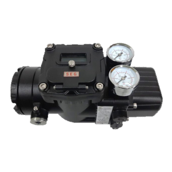
Page 7: Products Description
Smart Positioner SP760 Series Caution ▶ Operating the products incorrectly may be lower the safety. The well trained person who has proper knowledge and full experience on assembling and machinery operation should handle this products. ▶ Change or modification without permission may be exempt from the manufacturer's liability. -
Page 8: Options
Smart Positioner SP760 Series (1) Without opening cover, the LCD can be checked directly,so positioner condition can be checked visually. (2) Owing that 4 control buttons and button main function shall be adjusted in all mode of firmware interface, the using method is very simple. - Page 9 Smart Positioner SP760 Series ( IECEx, ATEX, NEPSI ) ( KCs ) Fig 2-2 SP760 Metal Label Items of Label Description Indicate model No according to specification Model No. including option. Indicate ambient temperature valid in explosion Ambient Temp. proof certification.
-
Page 10: Products Specification
Smart Positioner SP760 Series 2-5 Products Specification Model SP760S SP760D Acting Type Single Double Motion Type Linear Rotary Linear Rotary Input Signal 4~20mA DC Minimum Current Signal 3.2mA(Standard), 3.8mA(HART Included) Impedance Max.450Ω @ 20mA DC Air Connection NPT 1/4, PT 1/4(KCs for only) Pres. -
Page 11: Explosion Proof Certificate
- IECEx : IEC 60079-0:2017, IEC 60079-1:2014, IEC 60079-31:2013 - ATEX : EN 60079-0:2018, EN 60079-1:2014, EN 60079-31:2014 - KCs : Announcement No. 2020-33 of Ministry of Employment and Labor ※ Above all certification can be checked in homepage (www.seg.co.kr). - 10 - Ver 1.0... -
Page 12: Products Code
Smart Positioner SP760 Series 2-7 Products Code Model SP760 Acting Type Single Double Linear 20~80 mm 80~160mm Motion Type Rotary Standard Fork lever Namur Feedback None Position transmitter (4~20mA DC) Lock Condition Fail safe Fail Lock Explosion proof type Non Explosive type (IP66) - Page 13 Smart Positioner SP760 Series is connected to lower cylinder(28) while upper cylinder is connected to exhaust pipe raising piston rod(30) Lever(29) delivers a motion to output shaft (5) operating Pinion (23) and Gear(24) and rotating potentiometer(22) from which the resistance is fed back to control PCB(3).
-
Page 14: Structure
Smart Positioner SP760 Series Structure Figure 2-4 : Schematic View - 13 - Ver 1.0 SHINHWA Eng. -
Page 15: Products Dimension
Smart Positioner SP760 Series 2-10 Products Dimension Figure2-5 : SP760 Standard - 14 - Ver 1.0 SHINHWA Eng. - Page 16 Smart Positioner SP760 Series Figure 2-6 : SP760 Lever Type - 15 - Ver 1.0 SHINHWA Eng.
- Page 17 Smart Positioner SP760 Series Figure 2-7 : SP760 Fork Lever Type - 16 - Ver 1.0 SHINHWA Eng.
- Page 18 Smart Positioner SP760 Series Figure 2-8 : SP760 Namur Type - 17 - Ver 1.0 SHINHWA Eng.
-
Page 19: Installation
Smart Positioner SP760 Series 3. Installation 3-1 Caution before installation * When installing or replacing positioner equipped in actuator, please follow safety instructions. - Any input or supply pressure to valve, actuator and /or to other related devices must be turned off. -
Page 20: Standard Lever Type Positioner Installation Steps
Smart Positioner SP760 Series Figure 3-1 : SP760 Installation example Figure 3-3-2 Standard lever type positioner installation steps Figure 3-2 : SP760 positioner installation in actuator ① Assemble with the enclosed bracket and bolts. ② Connect a bracket onto actuator yoke with bolts. - Page 21 Smart Positioner SP760 Series Figure 3-3 : SP760 positioner installation in actuator ④ Connection bar located on actuator clamp should be inserted into spring position on feed back lever's hole as seen as figure. Figure 3-4 : Insert connection bar between lever and lever spring correctly.
- Page 22 Smart Positioner SP760 Series Figure 3-5 : Lever installed with vertically when valve stroke is 50% ⓐ Check valve's full stroke. ⓑ Make to correspondence connection bar in overall stroke value and feed back value's equal point. ⓒ If positioner lever and actuator connection bar has not consistent, move and re-set positioner bracket or connection bar.
-
Page 23: Rotary Positioner Installation
Smart Positioner SP760 Series 3-4 Rotary Positioner Installation Rotary positioner should be installed on 90 degree rotary motion valve such as rack pinion, scotch type ,ball valve or butterfly valve. There are Fork lever type and Namur type. Figure 3-7 : Fork Lever type... -
Page 24: Rotary Positioner Installation Steps
Smart Positioner SP760 Series 3-4-2 Rotary Positioner installation steps ① Connect up/down bracket assembles onto an actuator with bolts. Note the positioner manufacturer doses not supply bolts to fix an actuator. Actuator Up / Down bracket Counter clock and ② With an actuator's initial start point... -
Page 25: Connection -Air
Smart Positioner SP760 Series Connection - Air Pressure condition 4-1 Supply Caution ▶ Make sure that air filter regulator should be installed on the front of positioner. ▶ Supplying air should not be mixed with oil, moisture or impurities. ▶ Filter regulator pressure should be set 10% higher than actuator operation pressure or actuator spring operation pressure. -
Page 26: Double Acting Actuator
Smart Positioner SP760 Series 4-2-2 Double acting actuator Double acting positioner uses both OUT1 and OUT2 ports. If electric input signal shall be increased, air pressure is supplied from OUT1 port. So after checking this point, please note this when installing pipe. -
Page 27: Terminal Connection
Smart Positioner SP760 Series Flame explosion proof cable Figure 5-1 : Flame explosion proof cable 5-2 Terminal Connection AO : Analog Output IN(+) : Input signal (+) IN(-) : Input signal (-) AI : Analog Input FG : Frame ground... -
Page 28: Limit Switch Terminal
Smart Positioner SP760 Series 5-3 Limit Switch Terminal Figure 5-3 : Limit switch connection map 5-4 Ground - Ground must be done for positioner and system safety. - The ground terminal has each 1 ea / positioner internal and 1ea /positioner external They are assembled by M4 round head +bolt. -
Page 29: Adjustments
Smart Positioner SP760 Series 6. Adjustments 6-1 Limit Switch adjustment To adjust the operation location of limit switch, loosen the CAM fixed screw, and after CAM position should be rotated to desirable position and then tighten with screw again and fix. -
Page 30: Button Description
Smart Positioner SP760 Series 7-2 Button Description (UP&DOWN) : Movement to another menu or changing a parameter values in menu. (ENTER) : Enter into main menu or sub menu or designated parameter value. (ESC) : Return from the current menu to higher one step menu. -
Page 31: Manual Mode ( Manual )
Smart Positioner SP760 Series AUTO PV re-set Zero Point ( 0% ) and End point ( 100% ) only. --> Execute AUTO CAL without changing existing parameter. It is used when the positioner installation location is slightly required to modify. -
Page 32: Dead-Zone Mode ( Deadzone )
Smart Positioner SP760 Series AUTO CAL optimizes most of the actuator control values. However in case of special setting, only AUTO Calibration may be difficulty to optimize setting. if parameter set value shall be increased or decreased, it will be proper operation condition in current status. -
Page 33: Hand Calibration Mode ( Hand Cal )
Smart Positioner SP760 Series If increasing 100% ->0%, the operation velocity is adjusted to the target position. It is normally used when velocity is too far fast due to small actuator or when load friction shows down the lowering velocity . -
Page 34: Fb Norm
Smart Positioner SP760 Series Positioner's PV values can be same or reversely output with the actual stroke. EX ) NORM Mode current 0% shall be converted into 100% in case of REV. <UP 2 times> <ENTER> <UP>/<DOWN> → → →... -
Page 35: Valve Flow Characteristics Adjustment ( Char Ln )
Smart Positioner SP760 Series <ENTER 5 sec <ENTER> <ENTER> +UP 4 times> → → → <UP>/<DOWN> <ESC> <ENTER> → → ※ This work must be done after shut down air or 50% position condition. In this time ,actuator shall be operated reversely . -
Page 36: Tight Shut Open ( Tsht Op )
Smart Positioner SP760 Series <UP>/<DOWN> <UP 2 times> <ENTER> <ENTER> → → → <UP> <UP> <1 sec after> → → → <ESC> → 7-8-4 Tight Shut Open ( TSHT OP ) Tight Shut Open mode indicates the setting point as %. -
Page 37: View Mode (View)
Smart Positioner SP760 Series <UP>/<DOWN> <ENTER> <ENTER> <ENTER> → → → <ESC> → Set according to the connection method of single actuator and positioner. Ex )The above 8 standard lever type and adapter lever type is LEV setting while adaptor lever type and rotary type are STD setting. -
Page 38: Error And Warning Code
Smart Positioner SP760 Series Indication Description SP-760 Positioner model SP-4MIS V1.1 Current positioner version. It is total consumption time of products. But if power supply connection consumption time is below 4.18 1 minutes, it is not total calculated. 0Y Od 1st row : "3.11"... -
Page 39: Warning Code
Smart Positioner SP760 Series Indicate that PV is set 100 and lower. In the error happening case, Auto Calibration stops and the code is AIR CHK ERROR_03 displayed on LCD. Re-install to maintain the To release,use ESC button and follow positioner lever from the action steps. -
Page 40: Lcd Operation Map
Smart Positioner SP760 Series LCD OPERATION MAP - 39 - Ver 1.0 SHINHWA Eng. - Page 41 Smart Positioner SP760 Series SHINHWA ENG. Co., Ltd. Manufacturer information Company Name : SHIN HWA ENG Co., Ltd Address : 242 Cheongneungdae-ro ( 80B -2L ), Namdong gu, Incheon Korea ZIP CODE : 21695 : 82-32-817-8030 : 82-32-815-8036 E mail 8030@seg.co.kr...
Need help?
Do you have a question about the SP760 Series and is the answer not in the manual?
Questions and answers