
Summary of Contents for Olympic Hydro Drive
- Page 1 HYDRO DRIVE 360° UNIVERSAL DRIVE PARTS & MAINTENANCE Olympic Drives & Equipment Ltd. #120 - 6751 Graybar Road Richmond BC, Canada V6W-1H3 Telephone: 604-207-8444 Fax: 604-207-8441...
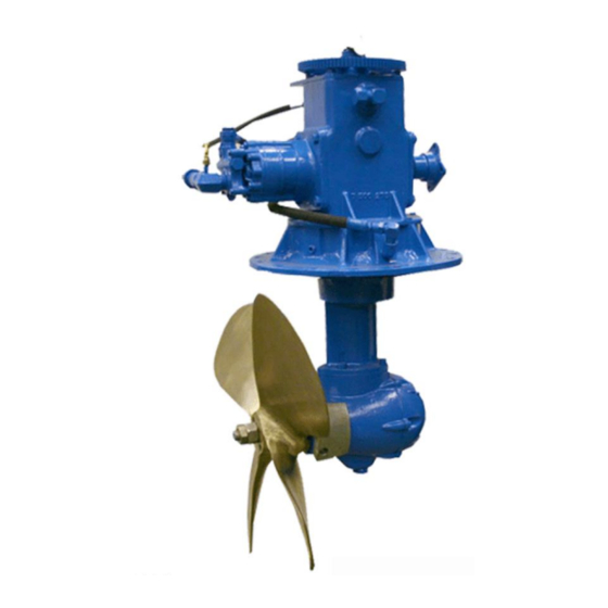
- Page 2 HYDRO DRIVE 360° AZIMUTH DRIVE SPECIFICATIONS Steering: 360° hydraulic power assisted Power Capacity, Continuous: Diesel: 100HP Propeller Clearance Radius: 13 Inches Customer-furnished (up to 24” diameter), R.H. rotation Propeller: 1 ½” standard taper Propeller Shaft: Weight: 280 lbs. Reduction Ratio:...
-
Page 3: Table Of Contents
Table of Contents General Information ........................... 4 Introduction .............................. 4 Description .............................. 4 SECTION II .............................. 5 Installation Instructions ........................5 GENERAL ............................... 5 INSPECTION ............................5 INSTALLATION ............................5 DRIVE SHAFT and UNIVERSAL JOINTS ..................6 SECTION III............................. 7 Propeller Installation &... -
Page 4: General Information
One set of gears is locked in the upper assembly and shear pin. Shear pins must meet housing and the second in the lower housing. The Hydro Drive Specifications (Part No. 1030-11). total reduction ratio is 2:1. The hydraulic system is comprised of a high-... -
Page 5: Section Ii
SECTION II Installation Instructions INSTALLATION GENERAL Install each drive as follows: The U360 Steerable Strut Drive mounts on any flat 1. Apply marine sealant liberally to mounting surface on the bottom of the vessel. The upper and surface on hull or apply rubber gasket. center housing assemblies are positioned inside 2. -
Page 6: Drive Shaft And Universal Joints
DRIVE SHAFT and UNIVERSAL JOINTS The drive input shaft is provided with a Spicer* Contact your local universal joint specialist for rectangular type companion flange (Part No. 3-1- recommendations on your installation and for 604). This flange is securely mounted to the drive proper selection of the 1410 Series universal joints, input shaft on a Standard S.A.E 1 ¼... -
Page 7: Section Iii
SECTION III Propeller Installation & Removal Procedure INSTALLATION REMOVAL (Always use puller) 1. Inspect propeller shaft seal for leakage (oil in 1. Remove cotter pin. drive). 2. Remove lock nut. 2. Inspect propeller bore and prop shaft for 3. Slack jam nut about ½”. cleanliness. -
Page 8: Operating Instructions
SECTION IV Operating Instructions b. Drive unit lubricant level. GENERAL c. Leakage (oil lines and connections). normal operating conditions, U360 d. Fasteners on drive and drive shaft. Steerable Strut Drive should be allowed to warm up before running under full power. Waiting for the While Running: engine to reach normal operating temperature with a. -
Page 9: Troubleshooting
Troubleshooting Trouble Probable Cause Remedy Vibration Bent propeller Straighten and balance propeller Drive shaft installed improperly Check that the universal joint forks are in the same plane (bearing holes in the same direction) Drive shaft has not been balanced Have drive shaft dynamically balanced Engine output shaft and drive input shaft Adjust engine mount so that shafts are parallel are not parallel... -
Page 10: Parts List
PARTS LIST ITEM PART NO. QTY. DESCRIPTION ITEM PART NO. QTY. DESCRIPTION Bearing – roller 5111 6106 Lock washer Cap – lower housing 7-500-103 5112 Bearing - needle Housing – center Bearing – inner race 7-500-253 5113 7-500-289 Zinc anode 5114 Bearing NO LONGER USED... - Page 11 [11]...
Need help?
Do you have a question about the Hydro Drive and is the answer not in the manual?
Questions and answers