Table of Contents
Advertisement
Quick Links
Advertisement
Table of Contents

Subscribe to Our Youtube Channel
Related Manuals for Tiso Optimus RB392 Series


Summary of Contents for Tiso Optimus RB392 Series
-
Page 2: Table Of Contents
CONTENT 1. Description of the Boom Barrier control units and electric parts ..............3 1.1. Purpose and operation of Boom Barrier control units and electric parts ............3 1.2. Description of the versatile controller PCB349 ....................4 1.2.1 Description of the PCB349 controller components ..................5 1.2.2 Description of controller contacts ........................ -
Page 3: Description Of The Boom Barrier Control Units And Electric Parts
1. Description of the Boom Barrier control units and electric parts The Boom Barrier shall be installed and connected to power supply network and other devices, maintained only by certified professionals carefully observing electrical and mechanical safety regulations. This Manual must be scrutinized prior to the Boom Barrier installation, connection, putting into operation and maintenance! 1.1. -
Page 4: Description Of The Versatile Controller Pcb349
1.2. Description of the versatile controller PCB349 Fig. 2 - Illustration of controller PCB349 with identification of its components, inputs and outputs... -
Page 5: Description Of The Pcb349 Controller Components
1.2.1 Description of the PCB349 controller components The controller PCB349 controls operation of devices by analyzing signals from potential inputs, angular position sensors and wire pushbutton control panel connected via interface RS485 and sets potential outputs depending on the Road Blocker status. Table 1 contains description of the PCB349 controller components Item Component... -
Page 6: Description Of Controller Contacts
1.2.2 Description of controller contacts X1 PS – Power Supply 230V Table 2 contains description of terminal block Power voltage 230VAC from switch B6. Circuit Breaker to be connected to terminal block X1 PS Power Supply 230V AC. Item Terminal name Purpose 230V AC IN PE Input for connection of protective earthing PE of power network voltage... - Page 7 Table 5 contains description of terminal block X5. INP1 The R o a d B l o c k e r 1 control inputs, sensors and additional devices to be connected to terminal block X5. INP1 – Inputs 1. Item Terminal name Purpose INP "UP"...
- Page 8 Table 6 contains description of terminal block X7. INP2 The Road Blocker2 control inputs, sensors and additional devices to be connected to terminal block X7. INP2 – Inputs 2. Item Terminal name Purpose 46 INP "UP" 2 The Road Blocker raising input. The Road Blocker will start raising when it is activated.
- Page 9 Table 7 contains description of terminal block X6. OUT1 The Road Blocker1 actuating and additional devices to be connected to terminal block X6. OUT1 – Outputs 1. Item Terminal name Purpose +12VDC +12VDC power voltage output for energization of actuating and additional devices.
- Page 10 Continuation table 8 TRAF. L. BOT OUT 2 The Road Blocker2 DOWN position output. It is active when the Road Blocker1 is in DOWN position. It is inactive when the Road Blocker1 is not in DOWN position. It can be used by access control system or for traffic light relay control. OUT 2 The Road Blocker 2 accumulator valve control output.
- Page 11 Table 10 contains description of switch The switch SW1- SW8 – Switch 1-8 is designed for selection of operation modes and setting of configuration parameters. Item Switch name Purpose Activation of the boom lift function if it did not reach the lower position during lowering Enabling the boom slow function at the end of the movement Duration of deceleration when lifting 1 or 2 seconds...
- Page 12 The PCB349 controller has two TIME1 (left) and TIME2 (right) regulators. The TIME1 regulator is used to adjust the timeout for raising and lowering. If the road blocker limit switches is not connected, - the road blocker will be started only for the time duration from 3 to 17 seconds, selected by the TIME1, after each raise or lower command, and will stop after this timeout has been completed.
-
Page 13: Connection Of Boom Barrier And Putting It Into Operation
2. Connection of Boom Barrier and putting it into operation In further description of Boom Barrier connection to control unit and other devices, connection and wiring diagrams the maximum configuration of accessories and options are specified. When in particular separate configuration some components are not used, then they just are not connected or not taken into account. - Page 14 The Boom Barrier stop or deceleration points during raising or lowering are determined by the of the position sensors position – limit switches and magnets. If appropriate, end position sensors to be adjusted according to the diagram shown in Fig. 5. Fig.5 - Adjustment of the Boom Barrier position sensors - limits switches and magnets.
-
Page 15: Troubleshooting
2.2. Troubleshooting Table 12 – Troubleshooting Item Malfunction Possible cause Action Boom Barrier motor B2-А1. Connections to be verified according to Motor connected description and diagrams in Annex 1 connected improperly to control and Annex 2 as well as errors to be unit eliminated and connection to be made Boom... -
Page 16: Wire Remote Control Panel Rb111
3.1. Wire remote control panel RB111 Fig. 8 - Front face of control panel RB111 The wire remote control unit RB111 can be used for the road blocker control. In general the control panel can control two independent devices connected to one control unit. Buttons "1 UP", "1 DOWN", "1 STOP"... -
Page 17: Boom Barrier Wireless Control
3.2. Boom Barrier wireless control The Boom Barrier control unit may include additional option – Boom Barrier wireless control by remote control pendants. In this case control unit includes B3-A3. Wireless Remote Controller Satel RE-2K * and scope of delivery includes some remote control pendants Satel T-2. Maximum allowable distance from remote control pendant to control unit is 25 m. -
Page 18: Protective Induction Loops
3.3. Protective induction loops The Boom Barrier control unit may include additional option – protective induction loops. One or two induction loops are installed in roadbed next to the Boom Barriers, are connected to control unit and are used to prevent the Boom Barrier raising when a vehicle is on induction loop. Fig.10 - Example of induction loop layout next to the road blocker If Boom Barrier has induction loop option, then control unit contains one or two controllers of induction loops B3-A4. - Page 19 Table 13 contains recommended induction loop size, number of turns and vehicle over induction loop detection height Length Width Turns Detection Height Feet 2 (0.61m) 2 (0.61m) 1.6 (0.488m) 2 (0.61m) 4 (1.22m) 1.6 (0.488m) 2 (0.61m) 6 (1.83m) 1.6 (0.488m) 2 (0.61m) 8 (2.44m) 1.6 (0.488m)
- Page 20 6 (1.83m) 40 (12.20m) 4.8 (1.463m) 8 (2.44m) 4 (1.22m) 3.2 (0.975m) 8 (2.44m) 6 (1.83m) 4.8 (1.463m) 8 (2.44m) 8 (2.44m) 5.6 (1.71m) 8 (2.44m) 10 (3.05m) 5.6 (1.71m) 8 (2.44m) 12 (3.66m) 5.6 (1.71m) 8 (2.44m) 14 (4.27m) 5.6 (1.71m) 8 (2.44m) 16 (4.88m)
-
Page 21: Road Blocker Operator's Guide
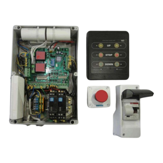
4. Road Blocker operator's guide The Boom Barrier can be controlled from operator control station, ordinary fixed pushbutton control box, 6-button control panel RB111 or wireless control pendant Satel RE-2K. Fig.12 - Ordinary fixed pushbutton control box (on the left) and 6-button control panel RB111 (on the right). Fig. - Page 22 The operator shall keep a close eye on availability of people or vehicle next to the Boom Barrier to avoid human injures by the Boom Barrier moving parts during generation of raising or lowering commands! The Boom Barrier can be also operated in automatic or semiautomatic mode along with access control system.
-
Page 23: Boom Barrier Electric Part Maintenance Instruction
5. Boom Barrier electric part maintenance instruction The Boom Barrier electric part maintenance is performed annually and includes: - Examination of the Boom Barrier components, motor, control unit, control boxes. - Cabling, electrical connection contact reliability, absence of mechanical damages of control unit to be visually inspected. -
Page 24: List Of Replacement Components In Case Of Failure
6. List of replacement components in case of failure A list of components with specified equivalents, which can replaced by certified service department in case of failure, is shown in Table 14. Table 14 - List of replacement components in case of failure Possible Position Quantity... -
Page 25: Annex 1. Boom Barrier Connection Diagram
Annex 1. Boom Barrier Connection Diagram... -
Page 26: Annex 2. Wiring Diagram Of Boom Barrier With Additional Devices
Annex 2. Wiring Diagram of Boom Barrier with additional devices...
Need help?
Do you have a question about the Optimus RB392 Series and is the answer not in the manual?
Questions and answers