
Related Manuals for Movacolor MC12-Micro

Summary of Contents for Movacolor MC12-Micro
- Page 1 MC12-Micro Software version : V1.08 Manual revision : v01 Language : English Date : February 2019...
-
Page 2: Table Of Contents
Symbols Terms Transport Receipt Disclaimer 2 General information Safety Certification Operating environmental conditions 3 Overview Dosing unit MC12-Micro Components overview. 4 Installation Mechanical Installation Electrical Connections Input (start) signal 5 Metering principle 6 Operation The Interface General Start up Configuration... -
Page 3: Introduction
Transport To protect the Movacolor unit against damage during transport, the unit is packed in a cardboard box filled with polyurethane foam. Delivery terms are Ex-Works Sneek, The Netherlands. Buyer is responsible for the transport. Movacolor cannot be held liable for any damage during transport. -
Page 4: General Information
Before switching on the unit for the first time, ensure that the mains power voltage applied is between 80 and 260VAC. Always switch off the Movacolor control cabinet and disconnect the mains power plug from electrical power before performing maintenance. -
Page 5: Overview Dosing Unit
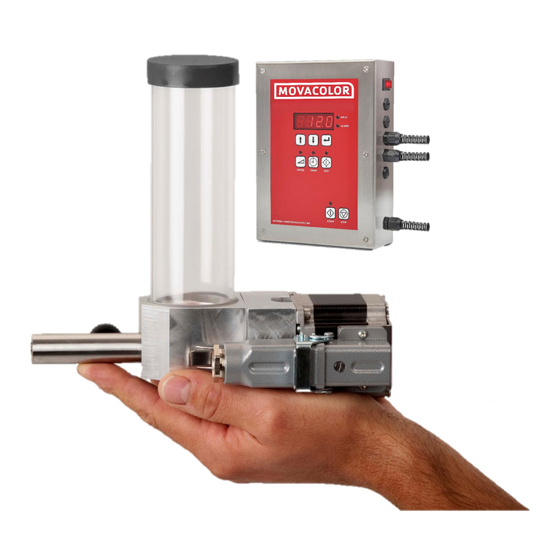
3 Overview Dosing unit MC12-Micro Components overview. Hopper cap Hopper Motor connector Seal Motor Motor spacer Dosing house Dosing Auger Dosing tube MC12 controller MC12 manual... -
Page 6: Installation
4 Installation Mechanical Installation Most mechanical parts are pre-assembled, making installation quick and simple. 1. When installing a foreign main material hopper on top of a neckpiece, the top flange of the neckpiece needs to be adapted. The lid of the neckpiece can be dismounted for easy machining. •... -
Page 7: Electrical Connections
Before switching on the unit for the first time, ensure the mains power voltage being applied is between 80 and 260Vac. Input (start) signal The MC12-Micro needs an input signal from the production machine in order to operate. Two different input signals can be used to control the dosing unit. -
Page 8: Metering Principle
5 Metering principle The Dosing Cylinder® of Movacolor combined with a very precise adjustable stepping motor ensures that the additive output is accurate and regular. For every particular application Movacolor provides different neckpieces but the most common mounting of the neckpiece is between the production machine and the hopper. -
Page 9: Operation
6 Operation The Interface Input LED. Is lighted when input connection is made. Alarm LED Increase / Decrease value Confirm value Set dosing speed [RPM] Run test Set dosing time [sec.] Stop system Start LED: Blinking: motor standby / waiting on start signal. -
Page 10: Start Up
Start up The MC12 software version is displayed shortly when the unit is switched on followed by the configuration mode (con). Configuration Type of Production Input signal Injection Molding Timer Extrusion Relay When the MC12 is set to configuration 2, the time function key is deactivated. -
Page 11: Alarms / Warnings
Production (Motor On/Off) Press to start production. The function active LED will start blinking when the unit is waiting for an input signal. The unit is dosing if the Start LED is lighted continuously. Test (Material output), can only be used when unit is stopped Test procedure to determine output of dosing system: •... -
Page 12: Maintenance
7 Maintenance To keep the MC12-Micro functioning correctly, it is advised to perform regular maintenance. Always switch off the control cabinet and disconnect the mains power plug from electrical power before performing maintenance. Weekly • Clean the dosing tool (cylinder or auger) for proper operation;... -
Page 13: System Performance
8 System performance The following variables may influence the accuracy and repeatability of the system: Material properties. Easy flowing, non-sticky and non-static material that comes in the form of small regular shaped granules or powder can be dosed very accurate and regular. Periodical cleaning of the dosing cylinder and seals is necessary for proper operation. -
Page 14: Appendix A: Mc12-Micro Technical Specifications
APPENDIX A: MC12-Micro Technical Specifications Controls: Speed: Manual setting from 0,1 to 200 RPM max, in increments of 0.1 RPM. Time: Manual settings from 0,1 to 999,9 sec in increments of 0,1 sec. Monitoring/System Information/External communication Man/Machine interface: 4-piece 7 segments LED at front display. -
Page 15: Appendix B: Mc12-Micro Wiring Diagram
APPENDIX B: MC12-Micro Wiring Diagram Input (start) signal = Yellow = Brown = White Potential free contact Potential contact [Min 18VDC to Max.24VDC] Motor Coil 1 Coil 2 Internal wires Main power switch Power Supply Western Europe USA,Canada,Mexico, Mid America,Japan,Taiwan ... -
Page 16: Appendix C: Mc12-Micro Dimensional Drawings
APPENDIX C: MC12-Micro Dimensional Drawings MC12 manual... -
Page 17: Appendix D: Declaration Of Conformity
APPENDIX D: Declaration of Conformity DECLARATION OF CONFORMITY (According to 2006/42/EC) Manufacturer’s name : MOVACOLOR BV Address : P.O. Box 3016 8600 DA Sneek The Netherlands www.movacolor.com Declare under our sole responsibility that the products: Product description : Dosing equipment...
Need help?
Do you have a question about the MC12-Micro and is the answer not in the manual?
Questions and answers