Table of Contents
Advertisement
Quick Links
UWAGA!
● Należy dokładnie zapoznać się z poniższą instrukcją przed
instalacją lub używaniem urządzenia.
● By uniknąć uszkodzeń i zagrożenia życia urządzenia
te powinny być instalowane przez wykwalifikowany personel,
i w zgodzie z odpowiednimi przepisami.
● Przed pracami serwisowymi, należy odłączyć wszystkie napięcia od wejść
pomiarowych i zasilania pomocniczego oraz zewrzeć zaciski przekładnika
prądowego.
● Produkty zaprezentowane w poniższym dokumencie mogą zostać zmienione
lub ulepszone bez konieczności wcześniejszego informowania o tym.
● Dane techniczne oraz opisy oddają w jak najdokładniejszy sposób posiadaną
przez nas wiedzę, jednak nie bierzemy odpowiedzialności za ewentualne błędy,
braki oraz sytuacje awaryjne.
● W układzie należy zamontować rozłącznik (wyłącznik), który musi znajdować
się niedaleko urządzenia i być łatwo dostępny dla operatora. Musi spełniać wymogi
następujących norm: IEC/ EN 61010-1 § 6.12.2.1.
● Należy umieścić urządzenie w obudowie lub szafie o minimalnym stopniu ochrony
IP40.
● Należy czyścić urządzenie delikatną suchą szmatką, nie należy używać środków
ściernych, płynnych detergentów lub rozpuszczalników.
Spis treści
Dok: I311PLGB1210_DMECD
PL
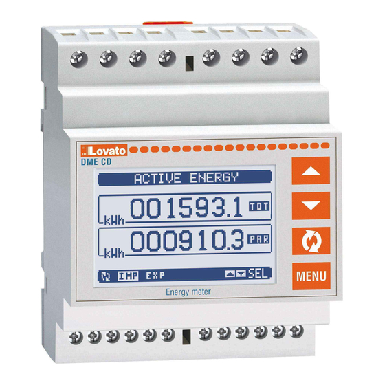
DME CD
Rejestrator danych
INSTRUKCJA OBSŁUGI
Strona
2
2
2
2
3
4
4
4
5
6
6
7
7
8
8
9
9
10
10
11
11
12
12
13
18
19
19
19
20
DME CD
Data concentrator
INSTRUCTIONS MANUAL
WARNING!
Carefully read the manual before the installation or use.
This equipment is to be installed by qualified personnel,
complying to current standards, to avoid damages or safety
hazards.
● Before any maintenance operation on the device, remove all the voltages from
measuring and supply inputs and short-circuit the CT input terminals.
● Products illustrated herein are subject to alteration and changes without prior
notice.
● Technical data and descriptions in the documentation are accurate, to the best
of our knowledge, but no liabilities for errors, omissions or contingencies arising
there from are accepted.
● A circuit breaker must be included in the electrical installation of the building. It
must be installed close by the equipment and within easy reach of the operator.
It must be marked as the disconnecting device of the equipment:
IEC /EN 61010-1 § 6.12.2.1.
● Fit the instrument in an enclosure or cabinet with minimum IP40 degree
protection.
●
Clean the instrument with a soft dry cloth; do not use abrasives, liquid
detergents or solvents.
Index
Hour counters page
Trend graph page
14/12/2010
Page
2
2
2
2
3
4
4
4
5
6
6
7
7
8
8
9
9
10
10
11
11
12
12
13
18
19
19
19
20
s. 1 / 21
Advertisement
Table of Contents

Related Manuals for LOVATO ELECTRIC DME CD

Summary of Contents for LOVATO ELECTRIC DME CD
-
Page 1: Table Of Contents
DME CD DME CD Rejestrator danych Data concentrator INSTRUKCJA OBSŁUGI INSTRUCTIONS MANUAL UWAGA! WARNING! ● Należy dokładnie zapoznać się z poniższą instrukcją przed Carefully read the manual before the installation or use. instalacją lub używaniem urządzenia. This equipment is to be installed by qualified personnel, ●... -
Page 2: Wprowadzenie
Wprowadzenie Introduction Rejestrator danych DMECD jest urządzeniem, które zwiększa potencjał The DMECD data concentrator is a device that extends the potential of zastosowania liczników energii serii DME, to jest umożliwia zbieranie DME energy meters family, providing a data collector function together danych i przesyłanie ich do systemu zdalnej kontroli. -
Page 3: Funkcje Rejestratora Danych
Funkcje rejestratora danych Functions of the data concentrator Rejestrator DMECD może zarządzać maksymalnie 16 licznikami, The DMECD can manage up to a maximum of 16 meters, określanych CNT01..16, każdy z licznikiem całkowitym (TOT) called CNT01..16, each with a total (TOT) and partial count i częściowym (PAR), oba z możliwością... -
Page 4: Funkcja Pochodnej
Włączanie pochodnej pomiaru Derivative measure enable Jeśli jest to wymagane to dla każdego licznika istnieje możliwość If required, for each count it is possible to have the indication wyświetlenia wskaźnika prędkości zmiany zliczania (pochodna). of the count change speed (derivative). Ta funkcja, na przykład, w klasycznym przypadku wskazania ilości For example in the classical case of indication of the quantity zużytej energii (kWh), umożliwia wskazanie aktualnej mocy średniej... -
Page 5: Wyświetlanie Pomiarów
przy użyciu funkcji matematycznych (+, - ,x ,/ ). into relation with one another with different mathematical operators (+, - ,x ,/ ). Zmienne matematyczne, następnie, mogą zostać wykorzystane, jako The mathematical variables can then in turn be used as ... -
Page 6: Strona Licznika Godzin
Strona graficzna trendów Trend graph page Strona graficzna trendów umożliwia wyświetlanie zmian w funkcji czasu The trend graph page allows to show the changes in the time domain jednego z pomiarów: of one measurement selectable among the following: Na wykresie mamy możliwość... -
Page 7: Menu Główne
Menu główne Main menu Menu główne składa się z grupy ikon graficznych (skróty), The main menu is made up of a group of graphic icons (shortcuts) that które umożliwiają szybki dostęp do pomiarów i ustawień. allow rapid access to measurements and settings. Po pojawieniu się... -
Page 8: Możliwość Rozbudowy
Możliwość rozbudowy Expandability Dzięki wybudowanemu portowi podczerwieni rejestrator DMECD może Thanks to its built-in optical infrared interface, the DMECD can be być rozbudowany o moduły rozszerzeń serii EXM…. expanded with EXM series modules. Moduły rozszerzeń posiadają port optyczny po lewej stronie, natomiast These modules have an optical interface on the left side for the ... -
Page 9: Kanały Komunikacji
TYP MODUŁU FUNKCJA IL. MAKS. MODULE TYPE CODE FUNCTION MAX Nr. KOMUNIKACJA EXM 10 10 COMMUNICATION EXM 10 10 EXM 10 11 RS-232 EXM 10 11 RS-232 EXM 10 12 RS-485 EXM 10 12 RS-485 EXM 10 13 ETHERNET EXM 10 13 ETHERNET CYF. -
Page 10: Progi Limitów
Progi limitów (LIM) Limit thresholds (LIM) Progi limitów LIMn są wewnętrznymi zmiennymi, których status zależy The LIMn thresholds are internal variables whose status depends on od przekroczenia limitów pomiarów zdefiniowanych przez użytkownika the out-of-limits of one particular measurement set by the user. Przykład: Pochodna licznika 1 (całkowita moc czynna) wyższa niż... -
Page 11: Zmienne Kontrolowane Zdalnie
Zmienne kontrolowane zdalnie (REM) Remote-controlled variables (REM) Rejestrator DMECD posiada możliwość zarządzania 8 zmiennymi, The DMECD can manage up to 8 remote-controlled variables kontrolowanymi zdalnie (REM1…REM8). (REM1…REM8). Status tych zmiennych może być modyfikowany przez użytkownika Those are variables which status can be modified by the user through ... -
Page 12: Taryfy
Taryfy Tariffs W celu zliczania energii DMECD może zarządzać 4 różnymi taryfami, For the Energy billing, the DMECD can manage 4 different tariffs in każda z licznikiem częściowym i całkowitym. addition to the total and partial Energy meters. Wybór taryfy dokonywany jest przez zewnętrzne wejście cyfrowe The tariff selection is made by external digital inputs or by the ... -
Page 13: Tabela Parametrów
Należy wybrać menu i wcisnąć przycisk by wyświetlić parametry. Select the sub-menu and press to show the parameters. Każdy parametr wyświetlony jest z kodem, opisem i aktualnie Each parameter is shown with code, description and actual setting ... - Page 14 P01.n.16 Dzielnik pochodnej 1-1000 P01.n.16 Derivative divider 1-1000 P01.n.17 Jednostka pomiaru (Tekst – 6 znaków) P01.n.17 Derivative unit of (Text – 6 chars) pochodnej measure Uwaga: To menu jest podzielone na 16 części, każda dla jednego licznika Note: This menu is divided into 16 sections, for counters CNT1..16 CNT1..16 P01.n.01 –...
- Page 15 P04.01 = Jeśli ustawiony na OFF licznik godzin jest wyłączony, a strona liczników P04.01 - If set to OFF the hour meter s are disabled and the hour meter page is not nie jest pokazywana. shown. P04.02 = Jeśli ustawiony na OFF, licznik godzin częściowy nie nalicza czasu. P04.02 - If set to OFF, the partial hour meter is not incremented.
- Page 16 Uwaga: To menu podzielone jest na 8 części, każda dla jednego progu limitów Note: This menu is divided into 8 sections, for limit thresholds LIM1..8 LIM1..8 P07.n.01 – Definiuje, który z pomiarów miernika musi być porównywany do limitów. P07.n.01 – Defines which measurement of the data concentrator must be compared with limits.
- Page 17 Uwaga: To menu jest podzielone na 16 części, każda dla jednego wejścia Note: This menu is divided into 16 sections, for digital inputs INP1..16 cyfrowego INP1..16 P10.n.01 = Funkcja wejścia: P10.n.01 = Input function: OFF – Wejście wyłączone OFF – Input disabled. ON –...
-
Page 18: Menu Komend
M13 – IMPULSY Domyślnie Zakres M13 – PULSES Default Range (PULn, n=1..5) PULn (n=1..5) P13.n.01 Źródło pomiaru P13.n.01 Source measurement CNT01-CNT16 CNT01-CNT16 MAT01-MAT16 MAT01-MAT16 P13.n.02 Jednostka zliczania 10/100/1k/10k P13.n.02 Count unit 10/100/1k/10k P13.n.03 Czas trwania impulsu 0.01-1.00 s P13.n.03 Pulse duration 0.01-1.00 s Uwaga: To menu jest podzielone na 5 części, każda dla jednego zliczania Note: This menu is divided into 5 sections, for count pulses PUL1..5... -
Page 19: Dane Techniczne
Pozycje zacisków i wymiary mechaniczne Terminals position and mechanical dimensions Dane techniczne Technical characteristics Zasilanie pomocnicze Auxiliary supply Napięcie znamionowe Us 100 - 240V~ Rated voltage Us 100 - 240V~ 110 - 250V= 110 - 250V= Zakres napięcia pracy 85 - 264V~ Operating voltage range 85 - 264V~ 93,5 - 300V=... -
Page 20: Schematy Połączeń
Ilość zacisków Number of terminals Przekrój przewodu (min i maks.) 0,2 - 2,5 mmq Conductor cross section (min… max) 0.2…2.5 mm² (24 - 12 AWG) (24 - 12 AWG) Moment obrotowy dokręcania zacisków 0.44 Nm (4 lbin) Tightening torque 0.44 Nm (4 lbin) Obudowa Housing Wersja... - Page 21 Podłączenie PC-DME CD.. przez port RS-485 PC-DME CD connection through RS-485 interface TR A RS485 RS485 DME CD n°31 DME CD n°1 Repeat this wiring diagram up to 255 devices TR A TR A TR A B TR A B SG...
Need help?
Do you have a question about the DME CD and is the answer not in the manual?
Questions and answers