
Related Manuals for MICROENER MM30-D

Summary of Contents for MICROENER MM30-D
- Page 1 Doc. N° MO-0037-ING MM30-D Rev. Date 24.02.2003 MICROPROCESSOR MOTOR PROTECTION RELAY WITH DIRECTIONAL EARTH FAULT ELEMENT TYPE MM30-D OPERATION MANUAL Copyright 2010 - Microener...
-
Page 2: Table Of Contents
20 Inverse time unbalance protection element___________________________________________________________ 30 21 Direction for pcb’s draw-out and plug-in_____________________________________________________________ 31 21.1 Draw-out______________________________________________________________________________ 31 21.2 Plug-in________________________________________________________________________________ 31 22 Overall dimensions / Mounting_____________________________________________________________________ 32 23 Keyboard operational diagram______________________________________________________________________ 33 24 Setting’s form____________________________________________________________________________________ 34 Copyright 2010 - Microener... -
Page 3: General Utilization And Commissioning Directions
The electronic circuits reduced by M.S. are completely safe from electrostatic discharge (8 KV IEC 255.22.2) when housed in their case; withdrawing the modules without proper cautions expose them to the risk of damage. Copyright 2010 - Microener... -
Page 4: Maintenance
The relay can be fitted with two different types of power supply module : 24V(-20%) / 110V(+15%) a.c. 80V(-20%) / 220V(+15%) a.c. a) - b) - 24V(-20%) / 125V(+20%) d.c. 90V(-20%) / 250V(+20%) d.c. Before energising the unit check that supply voltage is within the allowed limits. Copyright 2010 - Microener... -
Page 5: Operation An Algorithms
3 system C.Ts. or from the core balance C.T. 0) the Earth Fault Protection Element trips independently If any Earth Fault is experienced (I from the phase current measuring elements. Copyright 2010 - Microener... -
Page 6: Earth Fault Current And Voltage Inputs
The display directly gives the measurement “ Uo “ of the Secondary Zero sequence voltage and the measurement “ o ” of the phase displacement of the Zero Sequence Current Fasor from the Zero Sequence Voltage Fasor. Copyright 2010 - Microener... -
Page 7: Function And Setting
Automatic 1% drop out percentage. Restart inhibition: Ts/n = (40-100)%Tn, step 1%Tn To inhibit a new motor starting before cooling down to 99% Ts/n, reset after tripping of the thermal element takes places when T< 0.99[Ts]. Copyright 2010 - Microener... -
Page 8: F51Lr - Locked Rotor Protection (Rotor Jam)
This function performs the protection against no-load running: it is activated by motor under current. Under current level I< = (0.15-1)Im, step 0,01Im. lf I< = DIS. the function is disactivated. When current is below 0.1lm in all phases the function is activated. Trip time delay = 3 sec. Copyright 2010 - Microener... - Page 9 Doc. N° MO-0037-ING MM30-D Rev. Date 24.02.2003 Copyright 2010 - Microener...
-
Page 10: F51 - Overcurrent Protection
Overcurrent relay and the “ Uo “ level is disregarded. As for function F51, any of the output relays can be associated to the instantaneous element of “O>” as well as to the time delayed element “ tO> “. Copyright 2010 - Microener... -
Page 11: Limitation Of The Stats Number
At motor start counting of “ tTr “ begins. If during “ tTr ” the motor current drops below “ ltr “, switching-over is operated; if motor current stays above “ ltr “ longer than “ tTr “, the Locked Rotor element is activated. Copyright 2010 - Microener... -
Page 12: Autosetting
The complexity of properly set a motor protection, frequently produces undesired tripping or non-operation of some of the functions. The relay MM30-D can automatically select the best setting of the parameters according to motor and system basic data. These data are:... -
Page 13: Operational Of The Directional Earth Fault Element
The characteristic angle of the relay must be selected according to the kind of earthing of the installation which has to be protected against earth fault; typical setting are: o = 90° UNEARTHED NEUTRAL o = 0° NEUTRAL EARTHED VIA RESISTOR o = 60° SOLIDLY EARTHED NEUTRAL Copyright 2010 - Microener... -
Page 14: Clock And Calendar
During power on, time tolerance depends on the on board crystal (+/-50ppm typ, +/-100ppm max. over full temperature range). During power off, time tolerance depends on the RTC’s oscillator (+65 /–270 ppm max over full temperature range). Copyright 2010 - Microener... -
Page 15: Controls And Measurements
ENTER/RESET the relay has tripped, this button programming mode, allowing any resets the relay and all output or all of the relay’s settings to be contacts. If not tripped, this button altered. restores the default display. Copyright 2010 - Microener... -
Page 16: Signalization
Leds From flashing or illuminated to off, automatically when the lit-on cause disappears. In case of auxiliary power supply failure the status of the leds is recorded and reproduced when power supply is restored. Copyright 2010 - Microener... -
Page 17: Output Relays
This second unit REX-8 is configured (by internal Dip-Switch) to operate the eight relays two by two in parallel (only four user programmable outputs with double number of available contacts) Any of the functions featured by the MM30-D can be programmed to control up to four out of the sixteen user programmable output relays. -
Page 18: Serial Communication
Each relay is identified by its programmable address code (NodeAd) and can be called from the P.C. A dedicated communication software (MSCOM) for Windows 95/98/NT4 SP3 (or later) is available. Please refer to the MSCOM instruction manual for more information Microelettrica Scientifica. Copyright 2010 - Microener... -
Page 19: Digital Inputs
4 ms). If any internal fault is detected, the display shows a fault message, the Led "PROG/IRF" illuminates and the relay R5 is deenergized. Complete test activated by the keyboard or via the communication bus either with or without tripping of the output relays. Copyright 2010 - Microener... -
Page 20: Keyboard And Display Operation
- Yellow key ENTER/RESET : It allows the validation of the programmed settings the actuation of test programs the forcing of the default display indication the reset of signal Leds. e) - Indirect key : Enables access to the programming. Copyright 2010 - Microener... -
Page 21: Reading Of Measurements And Recorded Parameters
As above, phase C. As above, earth fault current. SoxxxxxA Sd/mxxx% Positive sequence current component at starting. Ss/mxxx% Negative sequence current component at starting. Measurement of the Motor Starting time. tStxxxxs SUoxxxxV Zero sequence voltage at starting. Copyright 2010 - Microener... -
Page 22: Trip Num
Enter the mode "SET DISP", select the menu "SETTINGS" or "F RELAY", scroll information available in the menu by keys "+" or "-". SETTINGS= values of relay's operation parameters as programmed RELAY= output relays associated to the different functions as programmed. Copyright 2010 - Microener... -
Page 23: Programming
Motor starting time Switch-over current of motor starter Dis – 0.1 – 1 ITr0.5Ist (p.u. of motor starting current) Max switch-over time from reduced to full voltage operation 0.5 – 50 tTr 6s during motor starting. Copyright 2010 - Microener... - Page 24 Enabling of input 1 – 3 for operation of the Speed Control function OFF – ON SpC OFF Clock synchronisation Time 5-10 Tsyn Dis m Expected time interval between sync. signal. 5 - 60 - Dis 15-30 60-Dis The setting Dis indicates that the function is disactivated. Copyright 2010 - Microener...
-
Page 25: Programming The Configuration Of Output Relay
R1, R2, R3, R4 tO> ---2 RA,RBRL Remote trip command (input 1-2) operates relay R1, R2, R3, R4 ---- RA,RBRL Time delayed Phase loss tripping operates relay R1, R2, R3, R4 1 ---1 RA,RBRL Copyright 2010 - Microener... -
Page 26: Manual And Automatic Test Operation
This is extremely important as discharges eventually tacking place in other parts or components of the board can severely damage the relays or cause damages, not immediately evident to the electronic components. Copyright 2010 - Microener... -
Page 27: Electrical Characteristics
Microelettrica Scientifica S.p.A. - 20089 Rozzano (MI) - Italy - Via Alberelle, 56/68 Tel. (##39) 02 575731 - Fax (##39) 02 57510940 http://www.microelettrica.com ute@microelettrica.com e-mail : The performances and the characteristics reported in this manual are not binding and can modified at any moment without notice Copyright 2010 - Microener... -
Page 28: Connection Diagram (Standard Output)
Doc. N° MO-0037-ING MM30-D Rev. Date 24.02.2003 16. CONNECTION DIAGRAM (SCE1423 Rev.2 Standard Output) 16.1 - CONNECTION DIAGRAM (SCE1499 Rev.0 Double Output) Copyright 2010 - Microener... -
Page 29: Wiring The Serial Communication Bus
Doc. N° MO-0037-ING MM30-D Rev. Date 24.02.2003 17. WIRING THE SERIAL COMMUNICATION BUS (SCE1309 Rev.0) 18. CHANGE PHASE CURRENT RATED INPUT 1 OR 5A Copyright 2010 - Microener... -
Page 30: Thermal Image Curves
Doc. N° MO-0037-ING MM30-D Rev. Date 24.02.2003 19. THERMAL IMAGE CURVES (TU0249 Rev.1) Copyright 2010 - Microener... -
Page 31: Inverse Time Unbalance Protection Element
Doc. N° MO-0037-ING MM30-D Rev. Date 24.02.2003 20. INVERSE TIME UNBALANCE PROTECTION ELEMENT (TU0248 Rev.1) Copyright 2010 - Microener... -
Page 32: Direction For Pcb's Draw-Out And Plug-In
Slide-in the card on the rails provided inside the enclosure. Plug-in the card completely and by pressing the handle to the closed position. Rotate anticlockwise the screws and with the mark in the vertical position (locked). Copyright 2010 - Microener... -
Page 33: Overall Dimensions / Mounting
Doc. N° MO-0037-ING MM30-D Rev. Date 24.02.2003 22. OVERALL DIMENSIONS / MOUNTING Copyright 2010 - Microener... -
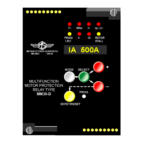
Page 34: Keyboard Operational Diagram
Doc. N° MO-0037-ING MM30-D Rev. Date 24.02.2003 23. KEYBOARD OPERATIONAL DIAGRAM Copyright 2010 - Microener... -
Page 35: Setting's Form
Enabling of the input 1 – 14 for operation of RTD OFF – ON function Enabling of input 1 – 3 for operation of the Speed OFF – ON Control function Clock synchronisation Time 5-60-Dis Tsyn Expected time interval between sync. signal. Copyright 2010 - Microener... - Page 36 Instantaneous earth fault tripping O> O> Time delayed earth fault tripping tO> tO> Remote trip command (input 1-2) Time delayed Phase loss tripping 1 1 Commissioning Engineer : Date : Customer Witness : Date : Copyright 2010 - Microener...
Need help?
Do you have a question about the MM30-D and is the answer not in the manual?
Questions and answers