
Subscribe to Our Youtube Channel
Related Manuals for Amber Wireless BlueNiceCom 4

Summary of Contents for Amber Wireless BlueNiceCom 4
- Page 1 Manual AMB2300 (BlueNiceCom4) Version 2.3 AMBER wireless GmbH Albin-Köbis-Straße 18 51147 Köln Tel. +49 (0) 2203-6991950 Fax +49 (0) 2203-459883 E-Mail info@amber-wireless.de Internet http://www.amber-wireless.de...
-
Page 2: Table Of Contents
Table of contents 1 Brief description ........................3 2 Technical data ........................3 2.1 Default settings ......................... 4 2.2 Pin assignment and functions ................... 4 2.2.1 Pinout ......................... 4 2.2.2 UART configuration with OP3, OP4, OP5 ..............5 2.2.3 UART interface RX_BT, TX_BT, RTS#_BT and CTS#_BT ......... 6 2.2.4 Details to the remaining connections of the AMB2300 .......... -
Page 3: Brief Description
Integrated profiles: SPP, GAP, SDAP Supported profiles: DUN, OBEX, HSP etc. AMBER wireless provides with the AMB2300 a certified, qualified listed Bluetooth-module, based on LMX9830 from National Semiconductor. This compact and inexpensive Bluetooth- module is qualified for a serial data or audio transmission. -
Page 4: Default Settings
2.1 Default settings All parameters are stored inside the internal EEPROM. See [1] and [2]. In the Bluetooth environmnent, the device announces itself as a BNC4-XXXXXX (Device Name), whereas XXXXXX has to be replaced by the device’s Bluetooth address. 2.2 Pin assignment and functions 2.2.1 Pinout Figure 1 Pinout Pin name... -
Page 5: Uart Configuration With Op3, Op4, Op5
RESETBB# Reset, internal Pull up, active low CTS#_BT Host Serial Port Clear To Send, active low RTS#_BT Host Serial Port Request To Send, active low TX_BT Host Serial Port Transmit Data RX_BT Host Serial Port Receive Data I/O GPIO (default setting as output, display a link connection) Not connected, no ground Power supply, 2.9V to 3.6V Antenna... -
Page 6: Uart Interface Rx_Bt, Tx_Bt, Rts#_Bt And Cts#_Bt
AMB2300 (BNC4) Example of circuit for OP3, OP4, OP5 BT-IC LMX9830 1KΩ 1KΩ Figure 2 Circuit suggestion 2.2.3 UART interface RX_BT, TX_BT, RTS#_BT and CTS#_BT The interface serves for communication with the AMB2300. Hardware handshake is used (RTS/CTS). If this should not be supported by the host system, RTS#_BT and CTS#_BT must be short circuit or CTS#_BT put on Low levels. -
Page 7: Block Diagram
2.2.5 Block diagram Figure 3 Block diagram 2.3 Dimension AMB2300 has 1mm x 2mm soldering pads with a grid of 2mm to be soldered direct on a motherboard. Figure 4 Dimensions 3 Hardware integration 3.1 Layout recommendation To achieve the maximum of range no metal (ground, strip line, components, etc..) has to be near the antenna, as shown hatched in the following figure. -
Page 8: Power Supply
distance of 8mm to any ground, strip line or component. Most suitable is to place the antenna at the margin of the motherboard. Figure 5 Antenna layout Caution: The AMB2300 is not isolated on the bottom side, so even if there are normally no short circuit problems because of the solder resist, an isolation should be placed between AMB2300 and motherboard in case of any copper on the top side of the motherboard underneath the AMB2300. - Page 9 o 250°C max. 20s (Chip-antenna) o 200°C max. 120s (Chip-antenna) The following drawing shows the example of the temperature curve of a 31cm² PCB assembled on one side. Figure 6 Example of a temperature curve Caution: Soldering profile has to be adapted corresponding to the conditions on the motherboard.
-
Page 10: Recommendation For Footprint
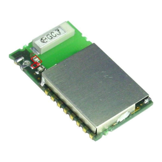
3.4 Recommendation for footprint Figure 7 Footprint, all dimensions in mm 3.5 External antenna The AMB2300 can be optionaly operated with an external antenna. In addition the red marked condenser (100pF 0603) must, as are changed above shown in its position. The lateral antenna connection is available then for a coaxial cable or a wire antenna. -
Page 11: Migration From Bnc3 To Amb2300 (Bnc4)
Figure 8 Placement of coupling capacitor 4 Migration from BNC3 to AMB2300 (BNC4) BNC3 AMB2300 (BNC4) CTS, RTS, TX, RX no change (UART) Vcc, GND no change Reset at BNC4 no external connection necessary ISEL2 PG6 (I/O) no connection necessary ISEL1 NC Pin not connected! ENV1... -
Page 12: Minimum Connection To Run The Amb2300
TX_Switch_p Audio interface, no connection necessary (PG7 fulfis these function now) VDD_DIGI_PER_D OP5 (Input) must be configured (UART configuration) OP4 (Input) must be configured (UART configuration) 5 Minimum connection to run the AMB2300 In order to realize a radio transmission, the following connections of the AMB2300 have to be wired: VCC, GND Power supply... -
Page 13: Regulatory Compliance Information
European Union's Radio & Telecommunications Terminal Equipment (R&TTE) directive. The conformity assessment of the subassembly AMB2300 carried out by AMBER wireless GmbH does not replace the required conformity assessment of the final product in accordance to the R&TTE directive! -
Page 14: Declaration Of Conformity
7.2 Declaration of conformity AMB2300 manual V2.3 14/16 Released: 28.01.2010... -
Page 15: Bluetooth Sig Qualification Design Certificate Qdid B013784
7.3 Bluetooth SIG Qualification Design Certificate QDID B013784 Figure 9 SIG QDL Certificate 7.4 Compliance statement FCC compliance statement This device complies with Part 15 of the FCC Rules. Operation is subject to the following two conditions: 1) This device may not cause harmful interference, and 2) This device must accept any interference received, including interference that may cause undesired operation. -
Page 16: Important Information
AMBER wireless GmbH customers using or selling these products for use in such applications do so at their own risk and agree to fully indemnify AMBER wireless GmbH for any damages resulting from any improper use or sale.
Need help?
Do you have a question about the BlueNiceCom 4 and is the answer not in the manual?
Questions and answers