
Related Manuals for Slot.it Universal Live Timing Box


Summary of Contents for Slot.it Universal Live Timing Box
- Page 1 Universal Live Timing Box Rev 2.0 User manual Figure 1: Universal Live Timing Box...
-
Page 2: Table Of Contents
18.1 Driver installation.........................45 18.2 Use of the Live Timing Box PC Interface application to communicate with the Universal Live Timing Box..........................46 18.2.1 Use the application to communicate with the Universal Live Timing Box....48 18.2.1.3 Download Language function................49 18.2.1.4 Download telemetry data function................49 18.2.1.5 Erase stored data function..................49... - Page 3 Box showing signs of tampering and/or not accompanied by the repair application (downloadable at www.slot.it ) totally filled in. This product is in accordance with RoHS guidelines. Do not dip it into water and do not put it in the microwave oven.
-
Page 4: Contents Of The Selling Pack
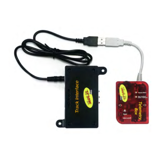
The presence of the Track Interface is necessary since the latter has the job of interfacing the Universal Live Timing Box with the track by collecting the signals coming from the sensors on the circuit (DS bridge, dead strip, Winchrono,...) and sending them after suitable elaboration to the Universal Live Timing Box itself. -
Page 5: Quickstart Audio Playback For The Impatient
3 Quickstart audio playback for the impatient Connect the Track Interface to your track’s sensors according to the relative manual. Connect the Universal Live Timing Box to the Track Interface through the “Track to Telemetry” cable. Connect the power supply to the Track Interface. -
Page 6: Universal Live Timing Box's Components Description
Universal Live Timing Box Rev 2.0 User manual 4 Universal Live Timing Box's components description Figure 3: Universal Live Timing Box: seen from the rear Figure 2: Universal Live Timing Box: seen of above Figure 5: Universal Live Timing Box: seen from the left... - Page 7 8. MP3 player input; 9. USB white cable: it allows to connect the Universal Live Timing Box to the SCP controller or to the “Track to Telemetry” cable of the Track Interface; 10. Audio Volume control: it allows the lap time playback’s volume control. The MP3 volume control is to be carried out on the MP3 player itself;...
- Page 8 12. reset: restart of the microcontroller in case of malfunctioning; Never connect the USB cable (10) of the Universal Live Timing Box to the USB ports of the PC. There’s no break hazard but the male USB of the Universal Live Timing Box is not a...
-
Page 9: Operation Description
“Track to telemetry cable” of the Track Interface (figure 7). Once the Universal Live Timing Box is powered, the LED (5) gives out a steady red light in order to show the user that the system is ready for use. -
Page 10: Lap Time Playback
It is also possible to hear lap time playback while the Universal Live Timing Box is connected to the PC , to PC Chrono, or PC Lap Counter. For the necessary connections, see paragraph 5.6 . -
Page 11: Data Storage On The Universal Live Timing Box's Internal Memory
The function of lap and possible sector times storage is available whatever controller is being used. In case that the Universal Live Timing Box is used together with a SCP-01 controller, it is also possible to see and store the data complete with telemetry. - Page 12 Figure 8: case b connections In order to enable the Data Storage function, press button (3) of the Universal Live Timing Box. The start of data storage is signalled by the Universal Live Timing Box through the flashing of LED(5) which keeps flashing for the entire duration of the storage.
- Page 13 "OFF". As for the mute button, also for the Mem on/off one the Universal Live Timing Box remembers the status the button is in before the supply is disconnected. This ensures that once the Universal Live...
-
Page 14: Erase Stored Data
Timing Box is unable to perform any other function; 2. Universal Live Timing Box powered by PC : in this case the user can delete the data stored on the Universal Live Timing Box only as indicated above in point 1 or through the Live Timing Box PC Interface software. -
Page 15: Universal Live Timing Box Firmware Updating
9. Czech; 10. multilingual (four languages). In order to set the Universal Live Timing Box on the chosen language, the system must be connected to the PC through a normal USB cable (type AB) (generic cable for printer). Moreover, nothing else can be connected to the Universal Live Timing Box. - Page 16 Universal Live Timing Box Rev 2.0 User manual 1. connect the Universal Live Timing Box to the PC with a generic USB cable (type AB) inserted into the USB port (6); 2. connect the SCP-01 controller to the Universal Live Timing Box by inserting the USB male plug of the latter (10) into the controller's USB connector;...
-
Page 17: Universal Live Timing Box Assembly On Scp-01 Controller
2. remove the frame on the back side of the shell, unscrewing the four screws; 3. insert the feet of the Universal Live Timing Box into the free holes on the back side of the shell;... -
Page 18: System Configuration With Pc Software
Universal Live Timing Box Rev 2.0 User manual 7 System configuration with PC Software Most of the ULTB features can be customised using the Live Timing Box PC Interface software. To do so, connect the ULTB to the PC through an USB cable, AB type (printer type), and follow the instructions found in the Live Timing Box PC Interface manual (paragraf 2.2.1.6) -
Page 19: Using The Live Timing Box Together With Pc Lap Counter
1. according to figure 7 o 8 depending on whether a SCP1 is used or not. 2. connect the Universal Live Timing Box to the PC through a standard USB - AB type cable, inserted in the USB female (6) of the ULTB Now launch PC Lap Counter (PCLC). -
Page 20: System Diagnostics
Universal Live Timing Box. If this happens, the electronic component has to be replaced; 3. red light flashing three times : the language in the memory of the Universal Live Timing Box is not recognized. It is therefore necessary to update the language of time playback. Refer to... -
Page 21: Universal Live Timing Box Firmware Updating Procedure
Figure 13: USB cable type AB Before the first Universal Live Timing Box updating, it's necessary to install the device driver, as explained better below. For the following updating , the procedure is the same except for the points number 8 and 9. - Page 22 Universal Live Timing Box Rev 2.0 User manual 3. plug the Universal Live Timing Box into the PC through the USB cable (not supplied – USB 2.0 AB cable (refer to the figure 13)). Please do not plug the white cable of Universal Live Timing Box into the PC USB port: it won't damage anything, but it just will not work! 4.
- Page 23 Universal Live Timing Box Rev 2.0 User manual Figure 16: Select the second option (“for expert users”) - and click on the “Avanti / Next” button. Figure 17:...
- Page 24 User manual Then select the first option and its second sub-option. Now click on the “Sfoglia / Browse” button and select the driver downloaded from the Slot.it web site. The driver name is atm6124_cdc.inf. Click on the “Avanti / Next” button.
- Page 25 Universal Live Timing Box Rev 2.0 User manual Figure 19: Now you can check the result of the driver installation: place the mouse cursor on the “My computer” icon found on the desktop and click on the mouse's right button. From the menu, select the “Property”...
- Page 26 Universal Live Timing Box Rev 2.0 User manual Figure 20: You are now ready to start the updating phase of the Universal Live Timing Box firmware. Please refer to the point number 10. 10. Launch the sam-ba_cdc_2.9.xp_vista.exe application by a double-click on its icon shown in figure 21 and the window shown in figure 22 appears.
- Page 27 11. Now you must select the board “at91sam7s64-ek” in the “Select your board:” menu, as shown in figure 22. Failing to do so will cause the Universal Live Timing Box to stop working, with no warning, seemingly dead after the programming procedure. Never mind –...
- Page 28 Universal Live Timing Box Rev 2.0 User manual Notes CE mark This device is compliant with the requirements of the CE mark for uses in residential districts, shopping precincts, vehicular and light industrial zones. RAEE / WEEE directive This symbol on the product or on the package indicates that this product must be separated from household-type waste.
- Page 29 Universal Live Timing Box Rev 2.0 User manual Figure 24: Track Interface.
- Page 30 – info@slot.it If it does not work, blame it on us. Slot.it and Slot.it logo are registered trademarks by Galileo Engineering S.r.l.. We thank you for choosing the Universal Live Timing Box system. Before operating, please read this manual attentively.
-
Page 31: Contents Of The Selling Pack
(DS bridge, dead strip...) which are on the track. In particular, it elaborates the signals given by the sensors so that they can be read by the Universal Live Timing Box, allowing the latter to carry out the expected functions, such as: lap time playback and time and telemetry data storage. -
Page 32: Description Of The Track Interface
Universal Live Timing Box Rev 2.0 User manual 13 Description of the Track Interface Figure 25: Track Interface: front view. Figure 26: Track Interface: back view. - Page 33 Universal Live Timing Box Rev 2.0 User manual Figure 27: Track Interface: right side view. With reference to the previous pictures, the following components can be distinguished: 1. “Bridge out” DIN plug: where a possible DS chrono can be connected by means of the "DS link cable";...
-
Page 34: Track Interface Power Supply
The sensors (lap and sector) must be positioned on the track at a time space of about six tenths of a second. [*] The Wincrono sensor requires a welding on the external shell of the female plug of the relative wiring. Refer to the relative file with the instructions, downloadable from the website www.slot.it 15.1 Connection to a DS bridge The Track Interface can be connected to a DS bridge. -
Page 35: Connection To A Dead Strip
DS chrono the times obtained by the DS bridge. Moreover, if the DS bridge has been chosen as lap counter sensor (see procedure at paragraph 16.1 ), the same displayed times will be reproduced in the earphones, if a Universal Live Timing Box has been connected to the Track Interface. -
Page 36: Connection To Slot.it Scp-01 Controller
"Track to Telemetry cable" of the Track Interface, included in the pack, and the "Connection cable" of the Universal Live Timing Box, included in the pack of the latter. Firstly, you have to weld the latter cable to the cartridge of the SCP-01 controller (for doing this, refer to the manual of the Universal Live Timing Box, paragraph 5.3). -
Page 37: Connection To The Slot.it Universal Live Timing Box
USB female plug of the "Track to Telemetry cable" of the Track Interface. The final result is shown in figure 31. Once the Track Interface is powered, the Universal Live Timing Box is powered, too. The user can check it by making sure that the LED (5) of the Universal Live Timing Box throws a red light. - Page 38 Expansion Cable; 5. according to the type of connection which has to be done (to Universal Live Timing Box or to SCP-01 controller) insert the USB male plug of the "Connection Cable" or of the USB white cable(10) of the Universal Live Timing Box into the USB female plug of the "Track to...
-
Page 39: Track Interface Setting
Universal Live Timing Box Rev 2.0 User manual 16 Track Interface setting The Track Interface allows the user to decide what role to give to the sensors, managed by the Track Interface, thanks to the double switch (5). In particular, with reference to the DS bridge sensors and dead strip sensors, the following combinations can be obtained: DS bridge lap sensor, dead strip sector sensor;... -
Page 40: Setting: Ds Bridge Sector Sensor, Dead Strip Sector Sensor
Universal Live Timing Box Rev 2.0 User manual 16.3 Setting: DS bridge sector sensor, dead strip sector sensor n order that the Track Interface interprets both DS bridge and dead strip as sector sensors, the double switch (5) must be set as shown in figure 35. - Page 41 Universal Live Timing Box Rev 2.0 User manual Notes CE mark This device is compliant with the requirements of the CE mark for uses in residential districts, shopping precincts, vehicular and light industrial zones. RAEE / WEEE directive This symbol on the product or on the package indicates that this product must be separated from household-type waste.
- Page 42 Universal Live Timing Box Rev 2.0 User manual...
- Page 43 The Live Timing Box PC Interface (also referred to as 'the software' in the manuals) software is a graphic interface allowing the user to carry out three types of operations: operations on the Universal Live Timing Box (also referred to as ULTB in the manuals) •...
-
Page 44: Installation Of Ltpcruntime
Universal Live Timing Box Rev 2.0 User manual 17 Installation of LTPCRunTime Download LTPCRunTime.zip. Decompress it and double click on setup.exe which can be found in the "Volume" directory. The installation of the runtime kernel begins. During this phase a series of... -
Page 45: Use Of The Live Timing Box Pc Interface Application
18.1 Driver installation When connecting the Universal Live Timing Box to the PC for the first time, through a generic USB cable (type AB), Windows requires the installation of the driver needed to communicate between the Live Timing Box PC Interface application and the Universal Live Timing Box itself. The name of the driver is LTBoxDriver.inf which should be downloaded from the Slot.it site, and placed in a... -
Page 46: Use Of The Live Timing Box Pc Interface Application To Communicate With The Universal Live Timing Box
Launche the application Live Timing Box PC Interface with a double mouse click - like any other application. If no Universal Live Timing Box (figure 38) is connected, connect the Universal Live Timing Box to the PC and push "OK". - Page 47 Universal Live Timing Box Rev 2.0 User manual In case of connected Universal Live Timing Box (figure 39), some information appears on the right side of the page: this is the first data exchange between the Live Timing Box PC Interface application and the Universal Live Timing Box.
-
Page 48: Use The Application To Communicate With The Universal Live Timing Box
Use the application to communicate with the Universal Live Timing Box If the Universal Live Timing Box is connected to the PC, the user can select the operation he wants to perform by the "Selected function" drop-down menu (figure. 40): 1. -
Page 49: Download Language Function
18.2.1.5 Erase stored data function To erase the data stored on the internal memory of the Universal Live Timing Box it is necessary to select "Erase stored data" from the "Selected function" drop-down menu. A warning message message then appears, reminding the user that all data stored in the internal memory of the Universal Live Timing Box is going to be erased. - Page 50 • lap time and lap number • best lap time and its number • firmware version of the SCP controller and Universal Live Timing Box in use; the type of cartridge connected to the controller; language of the Universal Live Timing Box.
- Page 51 Universal Live Timing Box Rev 2.0 User manual Figure 42: PC Chrono page. The buttons that can be found in the "Telemetry" page (figure 41): • Reset all: erase the data displayed in the following fields: Lap time, Lap number, Sector time, Sector number, Best time and Best lap;...
- Page 52 Universal Live Timing Box Rev 2.0 User manual Figure 43: postprocessing page. With reference to the "Postprocessing" page (figure 43), here is the meaning of each button: CLEAR TABLE: erase the just loaded table and file; • REFRESH TABLE: updates the loaded table;...
- Page 53 Universal Live Timing Box Rev 2.0 User manual Figure 44: postprocessing 2. As shown in figure 44, the buttons can be divided in three groups: DRIVER 1, DRIVER 2 and COMPARE. These are not enabled at the same time, but only as follows: those belonging to the first group, DRIVER 1, are enabled only if the user loads the data in •...
- Page 54 Universal Live Timing Box Rev 2.0 User manual ADD NEW LAP: click to select a further lap, so that it is possible to compare the data of the • two selected laps. The number of the additional selected lap can be seen in the "Selected 2 lap #"...
- Page 55 Universal Live Timing Box Rev 2.0 User manual 18.2.1.8 Live Timing Box Setting This function enables the writing of the internal EEPROM with custom values. Figure 45: If the box is connected and the Live Timing Box Setting is chosen, the following page appears on...
- Page 56 Universal Live Timing Box Rev 2.0 User manual Figure 46: The screen is split in three sections: 1. Current Live Timing Box settings (1): readout of the current state of the ULTB 2. New Live Timing Box setting (2): a description of the selected settings, as they will be written in EEPROM 3.
- Page 57 Universal Live Timing Box Rev 2.0 User manual The following parameters can be programmed in the ULTB EEPROM (Refer to Universal Live Timing Box manual (ver.2.0 or greater), chapter 7, for an explanation of the meaning of each parameter). 1. sample rate for telemetry data 2.
- Page 58 Universal Live Timing Box Rev 2.0 User manual 18.2.1.9 On-Line Live Timing Box PC Interface manual Click on the national flags in the 'User manual' screen area in the main window to access the online manuals. Figure 47:...
Need help?
Do you have a question about the Universal Live Timing Box and is the answer not in the manual?
Questions and answers