Table of Contents
Advertisement
Advertisement
Table of Contents

Related Manuals for RTS OMNEO Main Station


Summary of Contents for RTS OMNEO Main Station
- Page 1 OMS OMNEO Main Station Technical Manual...
-
Page 3: Table Of Contents
OMS OMNEO Main Station Table of contents | en Table of contents Safety Copyright and Disclaimer Notices Important safety instructions OMS Models Applicable products Model matrix Introduction OMS reference view Keypad reference view Installation System Interface Requirements Rack mounting instructions... - Page 4 | Table of contents OMS OMNEO Main Station 10.11 Mic kill 10.12 Info button 10.13 All call 10.14 All talk 10.15 Key assignment mode 10.16 SA keypad button 10.17 RSTP 10.18 Factory reset 10.19 Front panel reset button Download firmware 11.1...
- Page 5 OMS OMNEO Main Station Table of contents | en Configuration | Ports menu 22.1 Connect Devices 22.2 OMNEO channels 22.3 RVON channels 22.4 2-Wire ports Configuration | Audio menu 23.1 Headset Mic / Speaker 23.2 Panel mic / speaker 23.3 Filters 23.3.1...
- Page 6 | Table of contents OMS OMNEO Main Station 29.2 Setup pages 29.3 Scroll enables Intercom setup | Resources menu 30.1 Party line 30.2 30.3 Special list 30.4 Relay 30.5 Intercom setup | Gains menu 31.1 31.2 Crosspoint 31.3 Party line Intercom Setup | Alphas menu 32.1...
-
Page 7: Safety
OMS OMNEO Main Station Safety | en Safety Copyright and Disclaimer All rights reserved. The product information and design disclosed herein were originated by and are the property of Bosch Security Systems, LLC. Bosch reserves all patent, proprietary design, manufacturing, reproduction, use and sales rights thereto, and to any article disclosed therein, except to the extent rights are expressly granted to others. -
Page 8: Important Safety Instructions
| Safety OMS OMNEO Main Station Warning! To reduce the risk of fire or electric shock, do not expose this apparatus to rain or moisture. This product is AC only. CE Compliant and UL Certified Warning! This is a CLASS A product. In a domestic environment, this product may cause radio interference, in which case the user may be required to take adequate measures. -
Page 9: Oms Models
OMS OMNEO Main Station OMS Models | en OMS Models Applicable products This manual is applicable to these products: – OMS ANALOG 4M – OMS ANALOG 4F – OMS ANALOG 5F – OMS PLUS 4M – OMS PLUS 4F –... - Page 10 | OMS Models OMS OMNEO Main Station Both digital and wireless belt pack capacity comes out of this same pool of resources To determine the model running on the device, do the following: On the front of the OMS, press the MENU button.
-
Page 11: Introduction
Introduction | en Introduction The OMS Main Station is the beginning of a new era of intercom systems called RTS Digital Partyline. This powerful single system bridges legacy analog partyline users who wish to migrate to digital connectivity while using their existing equipment. Furthermore, OMS connects both wired and wireless intercom products. -
Page 12: Oms Reference View
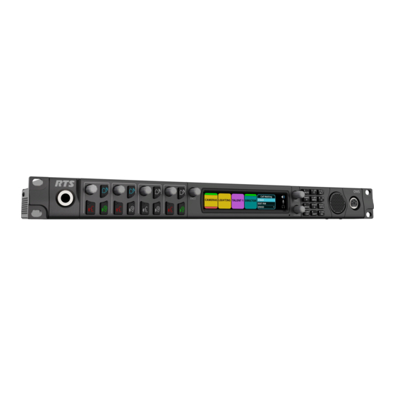
| OMS reference view OMS OMNEO Main Station OMS reference view Front panel Figure 4.1: OMS front panel reference view Key volume encoder knob Call button ENC1 encoder knob Left encoder knob High resolution LCD display ENC2 encoder knob Right encoder knob... - Page 13 OMS OMNEO Main Station OMS reference view | en Rear panel Figure 4.2: Rear panel reference view Control port Ethernet connector AC power connector 2W party line CH A, CH B, CH C, 3-pin XLR female connector and CH D PGM 1 input...
-
Page 14: Keypad Reference View
| Keypad reference view OMS OMNEO Main Station Keypad reference view There are three modes of operation for the keypanel keypad: Primary Mode and SHIFT Mode (DIAL mode is a secondary function of SHIFT Mode). Figure 5.1: OMS Keypad Primary Mode Use primary mode for the most common keypanel functions, such as CLR, SEL, and accessing the Main menu. - Page 15 OMS OMNEO Main Station Keypad reference view | en Keypad Mode Dial Mode Shift Mode Description MUTE The MUTE button mutes the panel microphone, headset microphone or both at the same time. The microphone mute operation can be configured as momentary, toggle or disabled.
- Page 16 | Keypad reference view OMS OMNEO Main Station Keypad Mode Dial Mode Shift Mode Description DROP Use the CLR button as a back button when a menu is displayed. Pressing the CLR/DROP button when in TIF DIAL mode hangs up the TIF connection.
-
Page 17: Installation
OMS OMNEO Main Station Installation | en Installation – If installed in a closed or multi-unit rack assembly, the operating ambient temperature of the rack environment may be greater than the room ambient temperature. Therefore, special consideration should be given to installing the equipment in an environment compatible with the specified maximum ambient operating temperature. -
Page 18: Rack Mounting Instructions
| Installation OMS OMNEO Main Station Rack mounting instructions Caution! Ensure the device is securely mounted to avoid uneven mechanical loading. Use all fasteners as defined in the instructions. To mount OMS in a rack, do the following: Use the four rack screws (not supplied) to secure OMS into the rack. -
Page 19: Cables And Cable Requirements
OMS OMNEO Main Station Cables and cable requirements | en Cables and cable requirements Connector pinouts Front Panel Connectors Panel Jack Signal Ring Panel Mic - Panel Mic + Sleeve Ground Tab. 7.3: Front Panel Microphone Jack Assignment Headset Microphone (-) - Page 20 | Cables and cable requirements OMS OMNEO Main Station Rear Panel Connectors Audiocom Clear-Com Ground Ground Ground Audio channel 1 (+30 V) Audio Hi (+24 V) (+30 V) Audio channel 2 (Optional +30 V) Audio Low (+24 V) Audio a.
- Page 21 OMS OMNEO Main Station Cables and cable requirements | en Assignment Silkscreen RELAY 1 common RELAY 1 normally closed RELAY 1 normally open RELAY 2 common RELAY 2 normally closed RELAY 2 normally open OPTO 1 anode OPTO 1 cathode...
- Page 22 | Cables and cable requirements OMS OMNEO Main Station Assignment Data 1 + Data 1 - Data 2 + Data 3 + Data 3 - Data 2 - Data 4 + Data 4 - Tab. 7.11: Control & RVON: J10...
-
Page 23: Tif And Legacy Keypanel Cable Overview
OMS OMNEO Main Station Cables and cable requirements | en TIF and legacy keypanel cable overview Each OMS system has unique requirements for cables, so it is not practical to apply these with the unit. Most of these cables need to be custom built. -
Page 24: Network Port Cabling
| Cables and cable requirements OMS OMNEO Main Station 1 The left LED is orange and indicates a 2 The right LED is bi-color (orange and network link is established. It flashes on/ green) and indicates the speed of the off whenever there is network activity. -
Page 25: System Configuration
OMS OMNEO Main Station System configuration | en System configuration Configure network ports To access the network configuration menu, do the following: Connect a power cord to the power connector on the rear panel of the device. The unit turns on, the display becomes active, and the device home screen appears. -
Page 26: Configure The Omneo Interface
| System configuration OMS OMNEO Main Station Configure the OMNEO interface To configure the OMNEO interface from the front panel, do the following: Navigate to the OMNEO icon. Click the ENC2 encoder knob. The OMNEO Configuration screen displays. Enter the Audio IP address used to transmit and receive audio across the network. -
Page 27: Configure The Rvon Interface
OMS OMNEO Main Station System configuration | en Configure the RVON interface To configure the RVON interface from the front panel, do the following: Navigate to the RVON icon. Click the ENC2 encoder knob. The RVON Configuration screen displays. Enter the IP address of the RVON interface. -
Page 28: Intercom Configuration
Select the desired mode. 10. Press the ENC2 encoder knob. 11. Navigate to the Loop field. (Optional) Modifications cannot be made to RTS 1 and RTS 2 modes. 12. Click the ENC2 encoder knob. The field is immediately toggled. 13. Navigate to the Auto-Mute field. (Optional) 14. -
Page 29: Connect 4-Wire Analog Devices To Oms
OMS OMNEO Main Station Intercom configuration | en 15. Click the ENC1 encoder knob to exit the screen. A Changes Made confirmation message displays. 16. Navigate to the desired action. Notice! Alternately, the ENC1 encoder knob can be clicked or the CLR button can be pressed to cancel this prompt and go back to editing the underlying screen. -
Page 30: Connect Omneo Devices To Oms
| Intercom configuration OMS OMNEO Main Station Navigate to the Connect All button. Navigate to the OMNEO device. Navigate to the Connect button. Click the ENC2 encoder knob. The OMNEO devices or the selected OMNEO device connects to OMS. -
Page 31: Connect Rvon Devices To Oms
OMS OMNEO Main Station Intercom configuration | en Navigate to the Port field. Click the ENC2 encoder knob. The field becomes active. Scroll to the desired port. 10. Click the ENC2 encoder knob. The field is changed. 11. Navigate to the Device Name field. - Page 32 | Intercom configuration OMS OMNEO Main Station Navigate to the RVON icon. Click the ENC2 encoder knob. The RVON Channels screen displays. Navigate to the Port field. Click the ENC2 encoder knob. The field becomes active. Scroll to the desired port.
-
Page 33: Add Devices To The Device Catalog In Ipedit
OMS OMNEO Main Station Intercom configuration | en 33. Select the VAD threshold level to use or to Off. 34. Click the ENC2 encoder knob. The field turns yellow (modification made, but not confirmed). 35. (Optional) Enter a description for this port connection. -
Page 34: Configure An Omneo Channel For Oms Using Ipedit
| Intercom configuration OMS OMNEO Main Station Select one or more available devices. The Add button becomes active. Notice! OMS (OMNEO) and OMS-R (RVON) device types are shown as separate devices in IPedit. The OMNEO and RVON interfaces may be on the same network (in which case IPedit can talk to... - Page 35 OMS OMNEO Main Station Intercom configuration | en In the Destination Device Name field, click the … button. The Discovered Devices screen displays. Expand the tree to view the destination devices available. Select the desired device for the destination. Click OK.
-
Page 36: Configure An Omneo Device To Connect To Oms
| Intercom configuration OMS OMNEO Main Station Using the Device Configuration Pane (Optional) Enter a description for the device. Send the changes to the device. 9.1.8 Configure an OMNEO device to connect to OMS Notice! Applicable for Basic, Intermediate, and Advanced models. -
Page 37: Configure An Rvon Keypanel To Connect To Oms
OMS OMNEO Main Station Intercom configuration | en Select the destination device type. Enter the IP address of the destination device. Select the channel to which the device connects. Select the codec to use. Select the packet size to use. -
Page 38: Configure Omneo Keypanels Using Ipedit
| Intercom configuration OMS OMNEO Main Station 9.1.11 Configure OMNEO keypanels using IPedit Notice! Applicable to the Basic, Intermediate and Advanced models. To configure OMNEO keypanel using IPedit, do the following: Using the Device Configuration Pane Enter a description for the device, if desired. -
Page 39: Configure Rvon Keypanels Using Ipedit
OMS OMNEO Main Station Intercom configuration | en Enter the name of the OMS device to which the channel will connect. Click the … button. The Discovered Devices screen displays. Expand the tree to view the destination devices available. Select the desired device for the destination. -
Page 40: Basic Operation
| Basic operation OMS OMNEO Main Station Basic operation 10.1 Navigating the menu The OMS menu structure separates into four logical sections: Status, Configuration, Intercom Setup, and Alarms. The menu is accessible using the keypad, the encoder knobs, or a combination of both. - Page 41 OMS OMNEO Main Station Basic operation | en Keypad MENU Home Port Status Menu Form Form Character/Mode screen Overview (navigating) (navigating) + SHIFT 6/RIGHT Rotate icon Move icon Move to next highlight CW highlight field (right) right 7/MICSEL Go to ALARM...
-
Page 42: Editing Field Data
| Basic operation OMS OMNEO Main Station Action / Mode Home Port Status Menu Form Form Overview (navigating) (navigating) + SHIFT Double-click Go to keypanel Go up one Move up Exit form screen level one menu (save level changes... - Page 43 OMS OMNEO Main Station Basic operation | en Keypad Field: Field+SHIFT: Field: Spinner Field: Field: Character / Text Text Pick List Check Box Mode 6/RIGHT Change Go to end of Move to next cursor text field (right) location 7/MICSEL 8/DOWN...
-
Page 44: Local Keypanel Icons
| Basic operation OMS OMNEO Main Station Keypad Form Form (editing) Form Form Form: Check Character / (editing): Text + SHIFT: Text (editing): (editing): Pick Mode Spinner List Press + Hold Activate Activate Activate Activate Activate screensaver screensaver screensaver... - Page 45 OMS OMNEO Main Station Basic operation | en Icon Icon Name Description Panel Speaker The panel speaker is enabled. Tone 1 kHz Enabled Tone 1 kHz is enabled on the local keypanel. Tone 500 Hz Enabled Tone 500 Hz is enabled on the local keypanel.
-
Page 46: Oms Menu Icons And Descriptions
| Basic operation OMS OMNEO Main Station 10.4 OMS menu icons and descriptions Display panel icons Notice! Some menus are only visible depending on the OMS model. Icon Icon Name Description Status Use the Status menu to view status information for the device. - Page 47 OMS OMNEO Main Station Basic operation | en OMNEO (SFP) The OMNEO (SFP) menu item displays the status details for the OMNEO SFP fiber ports. OMNEO (SFP), page 81 . OMNEO (RJ45) The OMNEO (RJ45) menu item displays status details for the OMNEO RJ45 ports.
- Page 48 | Basic operation OMS OMNEO Main Station Intercom Use the Intercom menu item to select the type of intercom status to view. See Status | Intercom menu, page 92 . GPIO The GPIO menu items displays GPIO input and output states.
- Page 49 OMS OMNEO Main Station Basic operation | en System Use the System menu to set or change the device name. See Configuration | System menu, page 98 . Intercom Name Use the Intercom Name menu item to rename the intercom system.
- Page 50 | Basic operation OMS OMNEO Main Station 2-Wire Ports Use the 2-Wire Ports menu item to configure the operating mode for the 2-wire ports. See 2-Wire ports, page 104 . Audio Use the Audio menu to configure local audio settings. Configuration | Audio menu, page 106 .
- Page 51 OMS OMNEO Main Station Basic operation | en generator checks the audio path from a device to the matrix. See Tone generator, page 115 . Key Volumes Use the Key Volumes menu item to adjust minimum crosspoint listen gains. See Key volumes, page 116 .
- Page 52 | Basic operation OMS OMNEO Main Station Display Options Use the Display Options menu item to configure panel volume and listen assignment displays. See Display Options, page 121 . User Preferences Use the User Preferences menu to configure device settings, such...
- Page 53 OMS OMNEO Main Station Basic operation | en Authentication Use the Authentication menu item to select different areas of the OMS device to configure security. See Authentication menu, page 128 . AZedit Use the AZedit menu item to restrict access to AZedit. See AZedit, page 128 .
- Page 54 | Basic operation OMS OMNEO Main Station Factory Reset Use the Factory Reset menu item to reset the device to factory settings. By default, this icon is hidden. To display this icon, see Factory reset, page 67 . Intercom Setup...
- Page 55 OMS OMNEO Main Station Basic operation | en Scroll Enables Use the Scroll Enables menu item to set up scroll enables and latch disables. See Scroll enables, page 142 . Resources Use the Resources menu item to select the assignment type to configure.
- Page 56 | Basic operation OMS OMNEO Main Station Port Use the Port menu item to view and edit the Alphas for each port assignment. Party Line Use the Party Line menu item to view and edit the Alphas for each party line assignment.
- Page 57 OMS OMNEO Main Station Basic operation | en – RVON, page 83 – Status | Ports menu, page 85 – OMNEO, page 85 – RVON, page 86 – AIO, page 87 – 2-Wire, page 88 – Devices, page 89 –...
-
Page 58: Port Status Overview
| Basic operation OMS OMNEO Main Station – Configuration | User Preferences menu, page 123 – Brightness, page 123 – Screen saver, page 123 – Alpha size, page 124 – Keypad, page 124 – Options, page 125 – Keypad hotkeys, page 126 –... -
Page 59: Link Status Overview
OMS OMNEO Main Station Basic operation | en Color Description Blue RVON Green Gold 2-Wire Magenta OMNEO Grey Port not licensed Icon Description Not configured (displayed as a square outline in the Port Type color) Configured, not connected Configured, connected, bi-directional audio... -
Page 60: Page Change
| Basic operation OMS OMNEO Main Station GREEN LED RED LED GREY LED CONTROL The link is up. The Control or RVON The LED is grey when RVON IP Address is no IP address specified, but none of (Control or Audio) is... -
Page 61: Party Line Call Window
OMS OMNEO Main Station Basic operation | en Figure 10.2: Page Change To change the page from the front panel, do the following: Press the SHIFT button. Press the PAGE button. The configured page tabs appear in the front panel display. -
Page 62: Call Waiting Window
| Basic operation OMS OMNEO Main Station Color Description Dark blue Non-selected call Light blue Selected call (not talking) Green Selected call (talking) To scroll the party line call list, do the following: When the party line call list is visible, rotate the ENC2 encoder knob to move through the scroll list. -
Page 63: Upg
OMS OMNEO Main Station Basic operation | en Incoming Calls When a call comes into the keypanel, the graphical CWW list appears on the keypanel display. The CWW retains call history for up to nine calls. The most recent call inserts at the top of the graphical CWW list and is highlighted. -
Page 64: Info Button
| Basic operation OMS OMNEO Main Station The mic kill function does not work on Clear-Com analog beltpacks. For information on disabling mic kill, please reference Keypad hotkeys, page 126 . To use mic kill, do the following: Enable the Party Line Talk button on the party line intended to receive the mic kill signal. -
Page 65: All Call
OMS OMNEO Main Station Basic operation | en 10.13 All call The ALL CALL button sends a call signal to party lines that are assigned to the OMS keys, including virtual keys not currently visible on the front panel. For devices connected to the OMS, ALL CALL causes an incoming call notification to the local user by a combination of visual, audio, or haptic notification. -
Page 66: Sa Keypad Button
| Basic operation OMS OMNEO Main Station Figure 10.5: Assignment Selection Mode Notice! Use the key volume encoder knob associated with the key assignment to change the assignment on a specific key. For example, to change key 1, operate key volume encoder knob 1, to change key 2, operate key volume encoder knob 2, and so on. -
Page 67: Rstp
OMS OMNEO Main Station Basic operation | en 10.17 RSTP RSTP (Rapid Spanning Tree Protocol) is a fault tolerant Ethernet protocol, which allows the system to be set up with multiple Ethernet connection paths to the same access points. This provides a redundant connection if one connection path fails. - Page 68 | Basic operation OMS OMNEO Main Station Refer to – OMS reference view, page 12 01-2021 | 03 | F.01U.380.820 Bosch Security Systems, LLC Technical Manual...
-
Page 69: Download Firmware
OMS OMNEO Main Station Download firmware | en Download firmware 11.1 Download firmware using AZedit To download firmware to the device, do the following: Open AZedit. Select Software Versions | Master Controllers from the Status menu. The Master Controller Version Information screen displays. -
Page 70: Download Firmware Using Firmware Upload Tool
| Download firmware OMS OMNEO Main Station Click Begin Download. The download begins. Once the image loads, a success message displays. Click OK. The screen closes. 10. Verify the firmware version is correct in the Master Controller Version Information screen. - Page 71 OMS OMNEO Main Station Download firmware | en Click Change. A network folder screen displays. Navigate to the folder containing the firmware files. Click OK. Click OK. The screen closes. Select the device to update from the Device page. Click Upload.
-
Page 72: Download Splash Screen
| Download firmware OMS OMNEO Main Station 11.3 Download splash screen To download a splash screen image to the device, do the following: Open AZedit. Select Software Versions | Master Controllers from the Status menu. The Master Controller Version Information screen displays. -
Page 73: Download Screen Saver
OMS OMNEO Main Station Download firmware | en Click Begin Download. The download begins. A progression bar appears to show the progress of the download. Once complete, a success message shows. Click OK. The message closes. The file is updated. -
Page 74: Download Licenses
| Download firmware OMS OMNEO Main Station Click Begin Download. The download begins. A progression bar appears to show the progress of the download. Once complete, a success message shows. Click OK. The message closes. The file is updated. - Page 75 OMS OMNEO Main Station Download firmware | en Select Download license… . The network folder opens. Navigate to the desired file. Click Open. The Download License File screen opens. Figure 11.1: Click Begin Download. The download begins. A progression bar appears to show the progress of the download.
- Page 76 | Download firmware OMS OMNEO Main Station Click OK. The message closes. The license is applied. 01-2021 | 03 | F.01U.380.820 Bosch Security Systems, LLC Technical Manual...
-
Page 77: Main Menu Access
OMS OMNEO Main Station Main menu access | en Main menu access The Home Screen is the top-most level of the menu structure. Figure 12.1: OMS Menu Home Available selections for this menu are: Status Menu Configuration Menu Intercom Setup Menu... -
Page 78: Status | System Menu
| Status | System menu OMS OMNEO Main Station Status | System menu Use the Status menu to view status information related to system, network, ports, peripherals, intercom, hardware, and key status. Figure 13.1: Status Menu System menu The System menu contains information about the firmware used in OMS, AZedit/IPedit sessions, and the intercom size. -
Page 79: Ipedit Sessions
OMS OMNEO Main Station Status | System menu | en Name Field The Name field displays the authenticated user name of the user connected. A login name is only required if authentication is enabled. Connection Field The Connection field displays the IP address of the computer running AZedit. - Page 80 | Status | System menu OMS OMNEO Main Station UPL Statements Field The UPL Statements field displays the number of UPL statements in the intercom system. The maximum number of UPL statements is 256. UPL Resources Field The UPL Resources field displays the number of UPL resources in the intercom system.
-
Page 81: Status | Network Menu
OMS OMNEO Main Station Status | Network menu | en Status | Network menu The Network menu item is used to view information about the following network connections: – Control Port – OMNEO (SFP) – OMNEO (RJ45) – RVON Figure 14.1: Status | Network | Menu 14.1... - Page 82 | Status | Network menu OMS OMNEO Main Station Figure 14.3: Status | Network | OMNEO_SFP Link A Column The Link A column displays the status for the Link A OMNEO (SFP) fiber connection. Link B Column The Link B column displays the status for the Link B OMNEO (SFP) fiber connection.
- Page 83 OMS OMNEO Main Station Status | Network menu | en No errors detected Tx Power Field The Tx Power field displays the amount of power used to transmit the outgoing optical signal. Rx Power Field The Rx Power field displays the amount of power being received from the incoming optical signal.
- Page 84 | Status | Network menu OMS OMNEO Main Station Figure 14.5: Status : Network : RVON screen Link Up Field The Link Up field displays the status of data communication on the RVON port. Available statuses are: The link is up...
-
Page 85: Status | Ports Menu
OMS OMNEO Main Station Status | Ports menu | en Status | Ports menu Use the Ports menu to view port status for the following port and device types: OMNEO RVON 2-Wire Devices Figure 15.1: Status | Ports | Menu Icons 15.1... - Page 86 | Status | Ports menu OMS OMNEO Main Station IP Address Field The IP Address field displays the IP address of the OMNEO device to which this port is connected. Rx Latency Field The Rx Latency field displays the latency of receive audio for this connection.
- Page 87 OMS OMNEO Main Station Status | Ports menu | en Channel Field The Channel field displays the channel number on the device to which this port is connected. VAD Field The VAD (Voice Activity Detection) field displays the threshold at which point audio transmits across the network.
-
Page 88: 2-Wire
| Status | Ports menu OMS OMNEO Main Station 15.4 2-Wire The 2-Wire screen displays status information for the four connectors, CH A, CH B, CH C, and CH D located on the rear panel of the device. Figure 15.5: Status | Ports | 2-Wire Screen Port Field The Port field shows the port alpha and the port number. -
Page 89: Devices
OMS OMNEO Main Station Status | Ports menu | en 15.5 Devices The Devices screen displays status information of connected devices. Figure 15.6: Status | Ports | Keypanel Port Field The Port field is used to select the port to view. - Page 90 | Status | Ports menu OMS OMNEO Main Station Status Field The Status field displays the status of the TIF. Available states are: Off-hook Ringing - (on-hook/idle) 01-2021 | 03 | F.01U.380.820 Bosch Security Systems, LLC Technical Manual...
-
Page 91: Status | Peripherals Menu
OMS OMNEO Main Station Status | Peripherals menu | en Status | Peripherals menu Use the Peripherals menu to access the status of GPIO-16 devices. Figure 16.1: Status : Peripherals Menu 16.1 GPIO-16 Figure 16.2: Status | Peripherals | GPIO16 Screen GPIO-16 Column The GPIO-16 column displays the number of the GPIO-16. -
Page 92: Status | Intercom Menu
| Status | Intercom menu OMS OMNEO Main Station Status | Intercom menu Use the Intercom menu to access the status pages for GPIOs and crosspoint inspections. Figure 17.1: Status : Intercom Menu 17.1 GPIO The GPIO screen displays status information for General Purpose Inputs and Outputs in the intercom. - Page 93 OMS OMNEO Main Station Status | Intercom menu | en Notice! To change the input port displayed, when the focus is on the input field, press the ENC2 encoder knob, and then turn the ENC2 encoder knob to scroll through port numbers.
-
Page 94: Status | Hardware Menu
| Status | Hardware menu OMS OMNEO Main Station Status | Hardware menu Use the Hardware menu to access status information for power supplies, device temperatures, and clock operation. Figure 18.1: Status : Hardware Menu 18.1 Power supplies The Power Supplies menu item displays power supply parameters for the different power supplies used by the device. -
Page 95: Temperatures
OMS OMNEO Main Station Status | Hardware menu | en Max Field The Max field displays the maximum current recorded on the power supply. This value resets at reboot. 18.2 Temperatures The Temperatures menu item displays temperature readings for different components inside the device. -
Page 96: Clock
| Status | Hardware menu OMS OMNEO Main Station 18.3 Clock The Clock menu shows the status of the OMNEO audio synchronization clock. Operation of OMNEO audio requires that all devices on the network have a synchronized clock reference. -
Page 97: Status | Key Status Menu
OMS OMNEO Main Station Status | Key Status menu | en Status | Key Status menu Use the Key Status screen to show various key configuration options on each key on the device. Figure 19.1: Status : Key Status Screen Listen Radio Button Use the Listen radio button to show the listen assignment on each key. -
Page 98: Configuration | System Menu
| Configuration | System menu OMS OMNEO Main Station Configuration | System menu Use the Configuration menu to configure system, network, port, audio, local keypanel, user preferences, and advanced settings. Figure 20.1: Configuration Menu System menu Use the System menu to access the Intercom Name screen. -
Page 99: Configuration | Network Menu
OMS OMNEO Main Station Configuration | Network menu | en Configuration | Network menu Use the Network menu to access the settings for the Control port, OMNEO port, and RVON port. Figure 21.1: Configuration : Network Menu 21.1 Control port The Control Port is used to configure the network connection to AZedit. -
Page 100: Rvon
100 en | Configuration | Network menu OMS OMNEO Main Station The controller and the audio device are tightly coupled. Failure to communicate between the controller and the audio device may cause unexpected results. Audio IP Field Use the Audio IP field to enter the IP Address used to transmit and receive audio across the network. - Page 101 OMS OMNEO Main Station Configuration | Network menu | en 101 Netmask Field Use the Netmask field to enter the netmask address. Gateway Field Use the Gateway field to enter the gateway address, if applicable. Bosch Security Systems, LLC 01-2021 | 03 | F.01U.380.820...
-
Page 102: Configuration | Ports Menu
102 en | Configuration | Ports menu OMS OMNEO Main Station Configuration | Ports menu Use the Ports menu to access configuration pages for OMNEO ports, RVON ports, and 2-wire ports. Figure 22.1: Configuration: Ports Menu 22.1 Connect Devices Use the Connect Devices screen to search for and select available OMNEO devices to add to the system. -
Page 103: Omneo Channels
OMS OMNEO Main Station Configuration | Ports menu | en 103 For more information, please refer to Connect OMNEO devices to OMS using Connect Devices, page 29 . 22.2 OMNEO channels Figure 22.6: Configuration | Ports | OMNEO Channels Port Field Use the Port field to select which port to configure. -
Page 104: 2-Wire Ports
104 en | Configuration | Ports menu OMS OMNEO Main Station IP Address Field Use the IP Address field to enter the IP address of the RVON device to which this port should connect. Codec Field Use the Codec field to select the codec type for the RVON port. - Page 105 Notice! When XLR-A and XLR-B are looped, this means both connectors are supporting the same pair of RTS-1 and RTS 2 channels and these ports to the intercom are port CH A and port CH B. Auto-Mute Field Use the Auto-Mute field to determine whether the 2W port automatically mutes. If the setting is enabled, the 2W port is muted whenever OMS detects the absence of DC power on the line (typically, because the cable on the 2W port was removed).
-
Page 106: Configuration | Audio Menu
106 en | Configuration | Audio menu OMS OMNEO Main Station Configuration | Audio menu Figure 23.1: Configuration : Audio Menu 23.1 Headset Mic / Speaker Use the Headset Mic / Speaker screen to configure how the headset microphone and speaker operates Figure 23.2: Configuration | Audio Menu | Headset Mic/Speaker Screen... - Page 107 OMS OMNEO Main Station Configuration | Audio menu | en 107 Type Field Use the Type field to select the type of microphone or allow the device to detect automatically the type of microphone connected. Available options are: – Auto-Detect (default) –...
-
Page 108: Panel Mic / Speaker
108 en | Configuration | Audio menu OMS OMNEO Main Station Available options are: – Enabled – Disabled – Switched (default) - Switched operation means the Mic Select key controls the state of the headset speaker. Mode Right Field The Mode Right field sets the state of the right headphone of the headset. - Page 109 OMS OMNEO Main Station Configuration | Audio menu | en 109 Figure 23.3: Configuration | Audio | Panel Mic/ Speaker Screen Microphone Section The Microphone section configures the panel microphone. Mode Field Use the Mode field to select the state of the panel mic.
-
Page 110: Filters
110 en | Configuration | Audio menu OMS OMNEO Main Station Compression Field Use the Compression field to change the audio's dynamic gain, meaning audio above the noise gate threshold changes according to the compression ratio selected. The compression changes the dynamic range of the mic input. In other words, loud sounds soften, while soft sounds amplify. -
Page 111: Panel Mic
OMS OMNEO Main Station Configuration | Audio menu | en 111 23.3.1 Panel mic Use the Panel Mic screen to configure a parametric equalizer on the panel mic. Figure 23.5: Configuration | Audio | Filters | Panel Mic Screen Enabled Check Box The Enabled check box determines whether the parametric equalizer is enabled. -
Page 112: Headset Mic
112 en | Configuration | Audio menu OMS OMNEO Main Station Band Gains 1 through 5 Field Use the Band Gains fields to adjust the gain for the selected frequency band. Available selections for this field: -6.0 dB to 0.0 dB. -
Page 113: Speaker
OMS OMNEO Main Station Configuration | Audio menu | en 113 An adjustable 5-band equalizer gives you the ability to adjust the low and high frequency cutoff filters and the gain for each band. This is in addition to the preset equalization settings on the local keypanel. -
Page 114: Headset Speaker
114 en | Configuration | Audio menu OMS OMNEO Main Station Default 0 dB (15 Hz to 20 kHz) Hiss Reduction 0 dB (15 Hz to 2 kHz) -6 dB (2 kHz to 12.6 kHz) Rumble Reduction 0 dB (50 Hz to 20 kHz) -
Page 115: Mic Options
OMS OMNEO Main Station Configuration | Audio menu | en 115 Low Frequency Field Use the Low Frequency field to set the low point of the frequency band. Available selections for this field: 50.0 Hz, 31.5 Hz, 15.6 Hz, or 0 Hz. -
Page 116: Key Volumes
116 en | Configuration | Audio menu OMS OMNEO Main Station – 1 kHz 23.6 Key volumes Use the Key Volumes menu to enable or disable the ability to adjust crosspoint listen gains. If enabled, users can adjust the listen gains for Matrix crosspoints using the key volume encoder knobs on the front panel. -
Page 117: Configuration | Local Keypanel Menu
OMS OMNEO Main Station Configuration | Local Keypanel menu | en 117 Configuration | Local Keypanel menu Use the Local Keypanel menu to access key options, auto dial, panel swap, page change, call waiting window, and display option configuration pages. -
Page 118: Auto Dial
118 en | Configuration | Local Keypanel menu OMS OMNEO Main Station Click the ENC2 encoder knob. Turn the ENC2 encoder knob to move the focus to Exclusive. Click the ENC2 encoder knob. Tap the desired talk key to assign the exclusive assignment. -
Page 119: Panel Swap
OMS OMNEO Main Station Configuration | Local Keypanel menu | en 119 Click the ENC2 encoder knob. Turn the ENC2 encoder knob to move the focus to the Number field. 10. Click the ENC2 encoder knob. 11. Enter the desired phone number. -
Page 120: Call Waiting Window
120 en | Configuration | Local Keypanel menu OMS OMNEO Main Station Figure 24.5: Configuration | Local Keypanel | Page Change Screen Mode Field Use the Mode field to select the action of the setup pages when talk keys are active. By default, page changes are allowed when talk keys are active. -
Page 121: Display Options
OMS OMNEO Main Station Configuration | Local Keypanel menu | en 121 unlatched when the footswitch releases. In this mode, the footswitch is a one-time operation. Pressing the footswitch turns the keys on and releasing the footswitch turns the keys off, unlatching them so the keys are unable to come on again with the next press of the footswitch. - Page 122 122 en | Configuration | Local Keypanel menu OMS OMNEO Main Station Show Listen Assignment Field Use the Show Listen Assignment field to enable or disable displaying listen assignments on the panel display. 01-2021 | 03 | F.01U.380.820 Bosch Security Systems, LLC...
-
Page 123: Configuration | User Preferences Menu
OMS OMNEO Main Station Configuration | User Preferences menu | en 123 Configuration | User Preferences menu Use the User Preference menu to access user preference configuration options such as brightness, screen saver usage, alpha display, keypad state color, information display options, keypad hotkeys, and signaling options. -
Page 124: Alpha Size
124 en | Configuration | User Preferences menu OMS OMNEO Main Station LCD Dim Delay Field Use the LCD Dim Delay field to set the amount of time before the LCD dims. When the screen saver or brightness dim mode becomes active, the key backlights also get dimmed. -
Page 125: Options
OMS OMNEO Main Station Configuration | User Preferences menu | en 125 Always Inactive The keypad backlight is always in the inactive state. When selected, the LED color/brightness does not change when SHIFT is pressed, even if the keypanel is in SHIFT mode. -
Page 126: Keypad Hotkeys
126 en | Configuration | User Preferences menu OMS OMNEO Main Station Notice! Not all screens have scroll bars. Only screens with more information than can fit on one display have the scroll bar capability. By default, Auto-Hide Scroll Bars is enabled. -
Page 127: Signaling
OMS OMNEO Main Station Configuration | User Preferences menu | en 127 Figure 25.7: Configuration : User Preferences : Keypad Hotkeys Screen Key 1 Call Enabled Check Box The Key 1 Call Enabled check box determines whether the key 1 call button operates. -
Page 128: Configuration | Advanced Menu
128 en | Configuration | Advanced menu OMS OMNEO Main Station Configuration | Advanced menu Use the Advanced menu to access configuration options for authentication, GPIO-16, clock, soft reboot, and diagnostics. There is a factory reset menu item that allows the device to be reset to factory defaults. -
Page 129: Ipedit
OMS OMNEO Main Station Configuration | Advanced menu | en 129 User Field Use the User field to select which user profile to view and modify. Up to 20 user profiles can be created. Admin Check Box The Admin check box determines whether the user profile has administrative rights. - Page 130 130 en | Configuration | Advanced menu OMS OMNEO Main Station Figure 26.5: Configuration | Authentication | Front Panel Notice! If the PIN is set, and then forgotten go to AZedit | Options | OMS Front Panel to reset the PIN.
-
Page 131: Debug Shell
OMS OMNEO Main Station Configuration | Advanced menu | en 131 26.1.4 Debug Shell Figure 26.6: Configuration | Authentication | Debug Shell Access Field Use the Access field to grant access to the debug. Telnet is available on the Control Port. -
Page 132: Soft Reset
132 en | Configuration | Advanced menu OMS OMNEO Main Station 26.4 Soft Reset Use the Soft Reset screen to reboot the device without resetting any of the configurations. To perform a soft reset, do the following: Navigate to the Soft Reset icon. - Page 133 OMS OMNEO Main Station Configuration | Advanced menu | en 133 Navigate to Diagnostics. Click the ENC2 encoder knob. Navigate to Test Panel. Click the ENC2 encoder knob. The Test Panel screen opens. Press any button on the front panel to test.
-
Page 134: Intercom Setup | Party Line Membership
134 en | Intercom setup | Party line membership OMS OMNEO Main Station Intercom setup | Party line membership Use Intercom setup to configure party line memberships, stored setups, devices, intercom resources, gains, and alphas. Notice! Changes made to the front panel settings save to flash immediately. However, it can take up to five minutes for changes made to the Intercom Setup to take effect. - Page 135 OMS OMNEO Main Station Intercom setup | Party line membership | en 135 Key State Description If the current assignment is being removed from the key and not being replaced, the current assignment toggles with a Null assignment (blue key with dashes).
- Page 136 136 en | Intercom setup | Party line membership OMS OMNEO Main Station Figure 27.4: Permanent talker/listener screen There are four configuration options for this screen. Assignment Description Talker The party line membership assignment is always talking. Listener The party line membership assignment is always listening.
-
Page 137: Intercom Setup | Stored Setups Menu
OMS OMNEO Main Station Intercom setup | Stored Setups menu | en 137 Intercom setup | Stored Setups menu Stored Setups are full AZedit setup files that are stored locally in the device and are recalled from the front panel (or AZedit) without having to send the file from AZedit. The device can configure, store, and save up to four setups (Slots). -
Page 138: Stored Setups Window
138 en | Intercom setup | Stored Setups menu OMS OMNEO Main Station Notice! The contents of a stored setup from OMS cannot be viewed. The Description field is used to describe in detail the saved setup parameters. To save a setup, do the following: Click the Stored Setups icon. - Page 139 OMS OMNEO Main Station Intercom setup | Stored Setups menu | en 139 Figure 28.3: Stored Setups screen from AZedit Notice! The Save, Restore, Delete, and Update Description buttons perform the same actions via AZedit as described for the front panel.
-
Page 140: Intercom Setup | Devices Menu
140 en | Intercom setup | Devices menu OMS OMNEO Main Station Intercom setup | Devices menu The Devices menu is used to configure keypanel assignments, key options and setup pages in the intercom system. Figure 29.1: Intercom Setup | Devices Menu 29.1... - Page 141 OMS OMNEO Main Station Intercom setup | Devices menu | en 141 Latch Disable Check Box The Latch Disable check box indicates the keypanel user cannot latch on the key. Clear the check box to enable latching capabilities. When Latching is enabled, the talk function stays on after the talk key is pressed briefly.
- Page 142 142 en | Intercom setup | Devices menu OMS OMNEO Main Station Notice! By default, modifications to setup pages are not allowed. Row Field The Row field displays the number of physical keys supported divided by 16. For example, a 64 key intercom shows four rows.
- Page 143 OMS OMNEO Main Station Intercom setup | Devices menu | en 143 Latch Disable Check Box The Latch Disable check box determines whether the selected device, when assigned to a key, causes the key to become latch disabled. Override this by clearing the latch disable for the key after the assignment is made.
- Page 144 144 en | Intercom setup | Resources menu OMS OMNEO Main Station Intercom setup | Resources menu Use the Resources menu to setup intercom resources in the intercom. Figure 30.1: Intercom Setup | Resources 30.1 Party line Use the Party Line screen to configure party line membership and options. A party line system is a system in which a number of participants are involved in the same conversation.
- Page 145 OMS OMNEO Main Station Intercom setup | Resources menu | en 145 Click the ENC2 encoder knob. The field becomes active. Select the desired party line. Click the ENC2 encoder knob to confirm. Navigate to the Scroll Enable check box.
- Page 146 146 en | Intercom setup | Resources menu OMS OMNEO Main Station Listen Field Use the Listen field to select the listen source port. The listen source is what a keypanel operator would hear when they listen to an IFB (if the listen assignment is an AT, Auto-Table).
- Page 147 OMS OMNEO Main Station Intercom setup | Resources menu | en 147 27. Click the ENC2 encoder knob to confirm the selection. 30.3 Special list Use the Special List screen to configure Special List membership and options. A special list is a way for a keypanel operator to talk or listen to several destinations using a single key.
- Page 148 148 en | Intercom setup | Resources menu OMS OMNEO Main Station 18. Click the ENC2 encoder knob to confirm the selection. 30.4 Relay Use the Relay screen to configure Relay definitions and options. Relay definitions must be made for each input port and an output port. The associated relay activates when the input port and output port crosspoint closes.
- Page 149 OMS OMNEO Main Station Intercom setup | Resources menu | en 149 Figure 30.6: Intercom Setup | Resources | ISO ISO Field Use the ISO field to select the ISO to configure. Output Field Use the Output field to enter the port number of the port to isolate when the ISO key is pressed.
- Page 150 150 en | Intercom setup | Gains menu OMS OMNEO Main Station Intercom setup | Gains menu Use the Gains menu to set I/O gains, crosspoint gains, and party line gains. Figure 31.1: Intercom Setup | Gains Menu Icons 31.1 Use the I/O screen to configure input and output gain for selected ports in the intercom system.
- Page 151 OMS OMNEO Main Station Intercom setup | Gains menu | en 151 13. Click the ENC1 encoder knob to exit the screen. A Changes Made message appears. 14. Navigate to the desired action. 15. Click the ENC2 encoder knob to confirm the selection.
- Page 152 152 en | Intercom setup | Gains menu OMS OMNEO Main Station Figure 31.4: Intercom Setup | Gains | Party Line Port Field Use the Port field to select the desired port’s party line listen gains to view or modify. Listening To Field Use the Listening To field to select the party line to which the selected port is listening.
- Page 153 OMS OMNEO Main Station Intercom Setup | Alphas menu | en 153 Intercom Setup | Alphas menu Figure 32.1: Intercom Setup | Alphas Menu Use the Alphas menu to view and modify the alphas for key assignment resource types. Configurable assignment types are Ports, Party Lines, IFBs, Special Lists, Relays, and ISOs.
- Page 154 154 en | Intercom Setup | Alphas menu OMS OMNEO Main Station Click the ENC2 encoder knob. Navigate to the 4 Character, 6 Character, 8 Character, or 8 Unicode field. Click the ENC2 encoder knob. Enter the desired Alpha in the active port field.
- Page 155 OMS OMNEO Main Station Alarms menu | en 155 Alarms menu The Alarms menu is used to access alarm notifications of events that occur in the intercom system. Figure 33.1: Alarms Menu When an alarm occurs, an Alarm Notification message appears on the front display. To clear this message, press the CLR button on the keypad.
- Page 156 156 en | Alarms menu OMS OMNEO Main Station Navigate to the Unacknowledged Alarms icon. Click the ENC2 encoder knob. The Unacknowledged Alarms list displays. Navigate to the desired alarm to acknowledge. Click the ENC2 encoder knob to confirm. Navigate to the Acknowledge button.
- Page 157 OMS OMNEO Main Station Alarms menu | en 157 Figure 33.6: Alarms | Active and Clearable and Non-Clearable Alarms To clear alarms from the Active alarm list, do the following: Navigate to the Active icon. Click the ENC2 encoder knob. The Active list shows.
- Page 158 158 en | Alarms menu OMS OMNEO Main Station 33.3 Alarm troubleshooting Alarm Popup Description Solution Check if: Lost contact with keypanel Lost contact with – The device powered off. <port alpha> (port <port keypanel – The device was physically number>)
- Page 159 OMS OMNEO Main Station Alarms menu | en 159 Alarm Popup Description Solution Check if: keypanel <port alpha> (port Keypanel has a – If the version string is <port number>) FPGA mismatch between appended with "R" (e.g. mismatch OMNEO and RVON 1.6.0R) then download the...
- Page 160 160 en | Alarms menu OMS OMNEO Main Station Alarm Popup Description Solution Check if: No MAC address defined for Depending on which – Power-cycle the OMS. Control port MAC address is missing, that network interface would not be operational.
- Page 161 OMS OMNEO Main Station Alarms menu | en 161 Alarm Popup Description Solution Check if: OMNEO device name change Dante Controller – If unintentional, change the changed the OMS's name back using the front OMNEO device name. panel, IPedit, or AZedit.
- Page 162 162 en | Technical data OMS OMNEO Main Station Technical data Power Supply Type : Locking IEC 320 C14 style connector AC Input: 100 VAC - 240 VAC, 60/50 Hz, 0.46 A / 0.24 A Maximum Power Consumption: 30 W (based on 120 VAC) Environmental Operating Temperature: 0 °C to +45 °C (+32 °F to +113 °F)
- Page 163 Output Noise Floor <-65 dBu Crosstalk Isolation >80 dB 2-Wire Party Line Analog Connector: Four, 3-pin female XLR connectors Modes / Ports Supported: RTS CH1, RTS CH2 Audiocom (4 channels) Clear-Com 4W / 2W Echo Return Loss: > 45 dB Unbalanced Operation (RTS/Clear-Com) Expected Termination Impedance: 200 Ω...
- Page 164 164 en | Technical data OMS OMNEO Main Station Balanced Operation (Audiocom) Expected Termination Impedance: 300 Ω Noise Floor Contribution: < -70 dBu THD+N (with nominal input): <0.5%, 200 Hz to 7.3 kHz Bridging Impedance: > 10 k Ω CALL Signaling: 20 kHz (Audiocom Mode)
- Page 165 OMS OMNEO Main Station Technical data | en 165 Bit Rate 64 kbps 8 kbps 64 kbps Coding Delay 125 µs 10 µs 4 µs Playout Delay 20-60 ms 20-120 ms 20-60 ms Bandwidth 160-224 kbps 32-112 kbps 160-224 kbps...
- Page 166 166 | Technical data OMS OMNEO Main Station 01-2021 | 03 | F.01U.380.820 Bosch Security Systems, LLC Technical Manual...
- Page 168 12000 Portland Avenue South Burnsville MN 55337 www.rtsintercoms.com © Bosch Security Systems, LLC, 2021 202101072108...
Need help?
Do you have a question about the OMNEO Main Station and is the answer not in the manual?
Questions and answers