Table of Contents
Advertisement
Quick Links
Advertisement
Table of Contents

Related Manuals for Embention TS150

Summary of Contents for Embention TS150
- Page 1 TS150 Embention Nov 03, 2020...
-
Page 3: Table Of Contents
..........TS150 Multicopter Control Panel . - Page 4 Maintenance Record ......... . . 4 Technical Part List .
-
Page 6: Installation
TS150 CHAPTER Installation Chapter 1. Installation... -
Page 7: System Overview
TS150 Ground Station and Multicopter 1.1 System Overview Multicopter, GS and PS 1.1. System Overview... -
Page 8: Components
TS150 Multicopter Isometric View Multicopter Multi View 1.2 Components Next figure shows the assembly of the system: Chapter 1. Installation... - Page 9 TS150 Assembly The main components of the system are: 1. Power station (PS): This is the case where the 230V AC wall input has to be connected and where the multirotor must be transported. 1.2. Components...
- Page 10 TS150 Power station Chapter 1. Installation...
- Page 11 TS150 Power Station with multicopter inside 2. Ground station (GS): is the place where the multirotor operates, it is ready to be used with Autopilot Veronte and Veronte PIPE systems. 1.2. Components...
- Page 12 TS150 Ground Control Station Chapter 1. Installation...
- Page 13 TS150 Top View 3. Multicopter: Y6 coaxial tricopter including our integrated gimbal. Custom payloads can be installed instead of the gimbal. Multicopter 1.2. Components...
-
Page 14: Dimensions And Weights
TS150 1.3 Dimensions and weights 1.3.1 Power Station Power Station Dimensions (mm) Multirotor inside 63.5Kg Empty 51.5Kg Power 4000W 1.3.2 Ground Control Station Ground Control Station and Power Station have the same dimensions. Weight 53Kg Power 600W 1.3.3 Cable Length... -
Page 15: Multirotor
TS150 1.3.4 Multirotor Multirotor 10.05Kg +Gimbal 11.8Kg +Gimbal + Cable 15.46Kg 1.4 Connections and controls 1.4.1 Power Station Power Station Connections 1.4. Connections and controls... - Page 16 TS150 Power Station Connections 3 pin connection 230V AC power output to GS 2 pin connection High voltage power output to GS Ground Switch Turns on/off the 230V AC power output to feed the GS Air Switch Turns on/off high voltage power output to feed the multicopter...
-
Page 17: Ground Control Station
TS150 1.4.2 Ground Control Station Ground Control Station Connections A Restart button Manually turns on/off the internal computer HDMI port Direct video output from the internal computer Ethernet port RJ45 LAN connector To connect any peripheral to the internal computer Fan and filter... -
Page 18: Multicopter-Cable
TS150 Ground Control Station Connections B 3 pin connection 230V AC output to GS 2 pin connection High voltage output to GS ROLL button Cable manual roll Stop button Cable manual stop 1.4.3 Multicopter-Cable Cable-Muticopter Connection Plug the connector from the GS into the multicopter... -
Page 19: Operation
2. Connect the ground control station to the multicopter. 3. Extend the cable out of the GS in an orderly manner. In future versions this wil be not necessary. 4. Power the TS150 turning on the ground switch. 5. Start Veronte Pipe. -
Page 20: Workspace
Above the motor information the operator can check the GNSS accuracy and on top of it the altitude as well as the vertical speed of the TS150. Motors information Altitude and climb rate Chapter 2. -
Page 21: Ts150 Multicopter Control Panel
TS150 available. 2.2 TS150 Multicopter Control Panel The TS150 multicopter control panel describes the flight phases of the TS150 multicopter and allows the operator to switch among them. TS150 Multicopter Control Panel Represented in green, it is the actual flight phase and in blue the different flight phases to which it is possible to switch. -
Page 22: Ts150 Gs Control Panel
GPS Lost: When the GNSS position is lost the TS150 multicopter will enter this phase until the signal is recovered. 2.3 TS150 GS Control Panel The TS150 GS Control Panel provides to the user the buttons required to roll and unroll the cable for storage purposes. TS150 GS Control Panel Icon... -
Page 23: Imu Calibration
TS150 2.4.1 IMU calibration The calibration menu can be opened directly from the Veronte Panel button and then 2.4.2 Magnetometer calibration To perform the magnetometer calibration open the calibration menu and select new window will appear and by clicking on start calibration, the system will start gathering information of the sensor. -
Page 24: Above Ground Level
TS150 Magnetometer calibration panel 2.4.3 Above ground level The above ground level measurement can be calibrated by selecting in the Veronte Panel and selecting . A new window will appear and after accepting the AGL reading will be calibrated. Ground reference panel... -
Page 25: Camera
If your TS150 system is equipped with an AIS receiver, the integrated model installed is a McMurdo Smartfind M15 model. Once the TS150 system is turned on, AIS system automatically starts working. There is no manual way of turn it on or off. -
Page 26: Emergency Battery Sytem Management
2.7 Emergency Battery Sytem Management The TS150 is equipped with an emergency battery system in case there is a ground power failure. Batteries have to be fully charged before the flight operation, if they are not fully charged the system will not allow you to fly. - Page 27 TS150 Multicopter Batteries Charging Port (Closed) 2.7. Emergency Battery Sytem Management...
- Page 28 TS150 Multicopter Batteries Charging Port (Opened) Custom Cable Connected To Charger Chapter 2. Operation...
-
Page 29: Weather Conditions
Once the batteries are fully charged, you are ready to flight. 2.8 Weather conditions TS150 is classified as IP53 device and this means it can be operated safely in light rain condition. As light rain criterion, the reference is considered to be the AEMET* description for “lluvia débil”... - Page 30 TS150 Chapter 2. Operation...
-
Page 31: Maintenance
Appendix H To facilitate this work we are going to explain the procedures and methods that you will have to follow. We will divide the maintenance of the TS150 in two parts: 3.1 Preventive Maintenance Preventive maintenance is required to ensure the optimal working state for the platform. -
Page 32: Pre-Flight Checking
TS150 3.2 Pre-flight Checking • Check all accessible screws are properly tighten. • Power line is connected properly through the MIL-DTL-26482 connector (Figure: Tether Connector and Figure: Power Line Connector) . Tether Connector Chapter 3. Maintenance... - Page 33 TS150 Power Line Connector • Payload is configured, ready to operate and fixed correctly. • Check the LEDs. • Air filters are clean. Two air filters must be checked. You can open the case pulling on one of its corners.
- Page 34 TS150 Lateral fans Chapter 3. Maintenance...
- Page 35 TS150 Opened case 3.2. Pre-flight Checking...
- Page 36 TS150 Take out the filter and clean them or replace them • Check the aircraft structure. – Fuselage without damage or fissures. – Arm connectors properly tightened and its security screws also. – Propellers screws properly tightened. – Landing gear without fissures.
-
Page 37: Post-Flight
• Open the drain situated on the bottom of the Ground Control Station, only in case of rain. Warning: TS150 can’t operate while it is raining. If you are operating and it starts to rain, you have to finish your operation immediately, keep the Tether in its Ground Control Station and open the drain. -
Page 38: Periodical Events
TS150 • After each flight use compressed air and/or a dry cloth to clean the complete system of dust and dirt. • If the system has contact with salty/marine ambient, do a special cleaning after each use. – Use a damp cloth with fresh water to remove the salt on the equipment. Never leave the equipment drying with salty water on it. - Page 39 TS150 Step 1 3. Disengage the arm by pulling it straight and parallel to its longitudinal axis. Be careful not to damage or deform bullet connectors. 4. Insert the new one. Be careful with the notch showed in Figure: Face 1 and Figure: Face: 2. Insert the arm by pushing it straight and parallel to its longitudinal axis.
- Page 40 TS150 Face 1 Chapter 3. Maintenance...
- Page 41 TS150 Face 2 5. Screw the nut and the set screws inserted in the nut. 3.4. Periodical events...
-
Page 42: Overhaul
TS150 Step 3 3.4.2 Overhaul Every 5000 flight hours an special inspection is necessary Check list: • Fully inspect all hardware components. • On the multicopter itself, you want to make sure there is no damage to gimbal, rotors, propellers, or other key components. -
Page 43: Corrective Maintenance
This procedures must be performed when some system or part of the aircraft has suffered damages. Warning: TS150 is a complex unmanned aerial system, for this reason we recommend to the user to perform only simple repairs. To solve other issues, please contact with Embention. - Page 44 TS150 NMTE008 Propellers Dynamometric Allen Key - 2.5 mm 1. Get a new one. Write to sales@embention.com asking for NMTE008 Propeller. Remember to specify if you need a top (Type L) or bottom (Type R) propeller. 2. Unscrew both metric screws (DIN 912) M3 that fix the propeller with the rotor.
- Page 45 TS150 Step 1 3. Disengage the damaged propeller. 3.5. Corrective Maintenance...
- Page 46 TS150 Step 2 4. Put the new propeller and screw it. Chapter 3. Maintenance...
- Page 47 TS150 Step 3 Warning: Pay attention to the propeller type correctly, logo and numbers have to be in the upper face always, as you can see in the Figure: Step 3. CW propeller in mounted on the upper motor and CCW propeller in the lower motor.
- Page 48 TS150 NMTE010 Landing Gear Chapter 3. Maintenance...
- Page 49 TS150 Dynamometric Allen Key - 2.5 mm Torque 2.6 N.m Warning: All the landing gears are the same. Front right and left are easy to repair and you can do it yourself following the next process. 1. Get a new one. Write to sales@embention.com...
- Page 50 TS150 Rear landing gear 1. Unscrew the M3 metric screws (DIN 912) [1]-[6], [11]-[14] and [19]-[22] 2. Disengage the broken landing gear. 3. Install the new landing gear. 4. Screw again all to the frame. Warning: Change batteries after an emergency landing. They are designed only for one use. Do not replace the battery while the multicopter is powered on.
- Page 51 TS150 Shell disassembly 1. Unscrew the M3 metric screws from the bracket. Battery bracket 1. Disconnect the battery. 2. Take out the damaged battery. 3. Install the new battery. 4. Screw again all to the frame. 3.5. Corrective Maintenance...
-
Page 52: Conditions Of Storage
Incidences happened during Pilot name and time Hours Hours the operation signature 3.8 Maintenance Record You have to use this Maintenance Record to collect data about the changes done in the TS150. Date Place of Total Maintenance Remarks of the Operator Signature... -
Page 53: Technical
CHAPTER Technical 4.1 Part List 4.1.1 Multicopter 4.1.1.1 Overview... -
Page 54: Exploded View
Complete Arm (Specify LED colour) NMTE010 Landing Gear NMTE007 Main Body VEGI005 Gimbal MRHE014 Propeller Kit CW+CCW CECN370 Cable-Multicopter Connector MTCA028 150m cable CEHW074 Custom filter Warning: Any different reference you are looking for, please contact Embention Chapter 4. Technical... -
Page 55: Ground Station
TS150 4.1.2 Ground Station 4.1.2.1 Overview TS150 Ground Station Overview 4.1. Part List... -
Page 56: Exploded View
TS150 4.1.2.2 Exploded View TS150 Ground Station 4.1.2.3 List Reference Description Quantity EMMA008 Case EMMA009 4 wheel kit MTME263 Threaded cover CEHW069 Dust Filter CEAN020 GPS Antenna CECN368 230V AC input plug CECN370 High voltage input plug Chapter 4. Technical... -
Page 57: Power Station
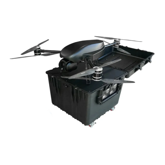
TS150 Warning: Any different reference you are looking for, please contact Embention 4.1.3 Power Station 4.1.3.1 Overview TS150 Power Station Overview 4.1. Part List... - Page 58 TS150 TS150 Power Station With Multicopter Chapter 4. Technical...
- Page 59 TS150 TS150 Power Station Ready to use 4.1. Part List...
-
Page 60: Exploded View
TS150 4.1.3.2 Exploded View TS150 Power Station 4.1.3.3 List Reference Description Quantity CEHW048 Emergency Stop Button EMMA008 Case EMMA009 4 Wheel Kit MTME269 Handle MTME270 M6 Knob Kit (4 units) MTME271 M5 Knob Kit (6 units) CECN362 230V AC input plug... - Page 61 TS150 TS150 Power Station Reference Description Quantity CEHW068 Dust filter Warning: Any different reference you are looking for, please contact Embention 4.1. Part List...
- Page 62 The NM& TS150 hexacopter is our multirotor tethered solution. The Tether Ground Station allows to power the UAV directly from an on-ground power source, providing unlimited flight time. Tether Station uses an innovative ultralight cable to connect the NM& TS150 drone to the ground station so the aircraft has a continuous power source during the operation.
- Page 63 TS150 NMAND TS150 Multirotor Tethered Station 4.1. Part List...
Need help?
Do you have a question about the TS150 and is the answer not in the manual?
Questions and answers