Table of Contents
Advertisement
Quick Links
Advertisement
Table of Contents

Related Manuals for Embention TS150

Summary of Contents for Embention TS150
- Page 1 TS150 Embention Dec 23, 2020...
-
Page 3: Table Of Contents
Contents 1 Installation System Overview ..........Components . - Page 4 3.5.3 Battery Replacement Unit maintenance ......Conditions Of Storage ......... . Flight Hours Record .
-
Page 6: Installation
TS150 CHAPTER Installation Chapter 1. Installation... -
Page 7: System Overview
TS150 Ground Station and Multicopter 1.1 System Overview Multicopter, GS and PS 1.1. System Overview... -
Page 8: Components
TS150 Multicopter Isometric View Multicopter Multi View 1.2 Components Next figure shows the assembly of the system: Chapter 1. Installation... - Page 9 TS150 Assembly The main components of the system are: 1. Power station (PS): This is the case where the 230V AC wall input has to be connected and where the multirotor must be transported. 1.2. Components...
- Page 10 TS150 Power station Chapter 1. Installation...
- Page 11 TS150 Power Station with multicopter inside 2. Ground station (GS): is the place where the multirotor operates, it is ready to be used with Autopilot Veronte and Veronte PIPE systems. 1.2. Components...
- Page 12 TS150 Ground Control Station Chapter 1. Installation...
- Page 13 TS150 Top View 3. Multicopter: Y6 coaxial tricopter including our integrated gimbal. Custom payloads can be installed instead of the gimbal. Multicopter 1.2. Components...
-
Page 14: Dimensions And Weights
TS150 1.3 Dimensions and weights 1.3.1 Power Station Power Station Dimensions (mm) Multirotor inside 63.5Kg Empty 51.5Kg Power 4000W 1.3.2 Ground Control Station Ground Control Station and Power Station have the same dimensions. Weight 53Kg Power 600W 1.3.3 Cable Length... -
Page 15: Multirotor
TS150 1.3.4 Multirotor Multirotor 9.55Kg +Gimbal 11.3Kg +Gimbal + Cable 14.96Kg 1.4 Connections and controls 1.4.1 Power Station Power Station Connections 1.4. Connections and controls... - Page 16 TS150 Power Station Connections 3 pin connection 230V AC power output to GS 2 pin connection High voltage power output to GS Ground Switch Turns on/off the 230V AC power output to feed the GS Air Switch Turns on/off high voltage power output to feed the multicopter...
-
Page 17: Ground Control Station
TS150 1.4.2 Ground Control Station Ground Control Station Connections A Restart button Manually turns on/off the internal computer HDMI port Direct video output from the internal computer Ethernet port RJ45 LAN connector To connect any peripheral to the internal computer Fan and filter... -
Page 18: Multicopter-Cable
TS150 Ground Control Station Connections B 3 pin connection 230V AC input to GS 2 pin connection High voltage input to GS ROLL button Cable manual roll Stop button Brake enable / Brake disable 1.4.3 Multicopter-Cable Cable-Muticopter Connection Chapter 1. Installation... - Page 19 TS150 Plug the connector from the GS into the multicopter. Warning: It is important to ensure that there are at least 2 meters of cable out of the ground station before taking off. This will avoid problems in the operation.
- Page 20 TS150 Chapter 1. Installation...
-
Page 21: Operation
CHAPTER Operation This document is intended to describe the functionalities of the Tethered App The first step to work with Tethered App is to open a Microsoft Edge or Firefox Browser and go to the url: 192.168.1.127:5000 Note: It’s preferable to use Microsoft Edge to correctly view the video 2.1 System check System check fail... - Page 22 TS150 1- Sensors Checklist: This menu is used to check the IMU and Magnetometer values are in ok, calibrate de atmosphere (MSL) and set the landing point. For calibrate IMU and magnetometer, please visit https://manuals.embention.com/Veronte_Autopilot/en/latest/ operation/commands/quick-commands/index.html 2- Status: These fields represent if the power sources are connected and if the battery has enough voltage. The batteries haved are in green for ready to fly, if any power source are in red, please check the power source in the...
-
Page 23: Operation Window
TS150 2.2 Operation window Operation Window 1- Height controls: Controls to make the platform go up and down and set the takeoff desired height. 2- Phase controls: From here you can control the drone with his phases. • Arm: Arm the platform. -
Page 24: Artificial Vision Controls
TS150 8- Geotagging: You can save some points with the geotagging option and point later with the gimbal. 9- Gimbal controls: To move the gimbal wherever you want. 2.3 Artificial Vision controls 1- Zoom predefined: These buttons are predefined zooms to go to this zoom position with one click. -
Page 25: Settings Panel
TS150 Tracking Moving 4- Gimbal mode: With this option you can choose or manually control the gimbal or point to any location, with the last option you can put any know coordinate or click on the image to get the coordinates of what you are seeing in the image and point to them. - Page 26 TS150 - Landing point Distance: The distance zero is the center (GS) of the compass. Can move the distance around 15 meters from the center (GS). Distance landing from GS (7 meters, 1 degree north) Distance landing from GS (10 meters, 52 degree north-east)
- Page 27 TS150 Landing about GS (0 meters) - Atmosphere calibration: Calibrate the atmosphere, enter the altitude MSL (Mean Sea Level) and temperature and press apply. - General settings: Enable or disabled show point coordinates and choose the platform coordinates units between Decimal, Sexagecimal, UTM and MGRS coordinates.
-
Page 28: Rendesvouz Configuration
TS150 of detection range. - Rendezvous position: This panel is to put the relative points in the rendezvous phases. Explained in the following sections. 2.5 Rendesvouz configuration - Rendezvous Landing position: The landing maneuvre is made up of two points that are defined relative to the actual Ground Station position (z down). - Page 29 TS150 Landing Rendesvouz relative position configuration: (X = 0) (Y = 0) (Z = -2) Landing Docking relative position configuration: (X = 0) (Y = 0) (Z = 100) 2.5. Rendesvouz configuration...
- Page 30 TS150 Landing Rendesvouz relative position configuration: (X = 3) (Y = 0) (Z = -2) Landing Docking relative position configuration: (X = 3) (Y = 0) (Z = 100) Chapter 2. Operation...
- Page 31 TS150 Landing Rendesvouz relative position configuration: (X = 3) (Y = 3) (Z = -2) Landing Docking relative position configuration: (X = 3) (Y = 3) (Z = 100) - Rendezvous Hover position: The relative hover phase makes the multicopter kept a determined position defined relative to the location of the GS station.
- Page 32 TS150 Hover relative position configuration: (X = -30) (Y = 0) (Z = -130) Chapter 2. Operation...
-
Page 33: Geolocation Configuration
TS150 Hover relative position configuration: (X = 0) (Y = 0) (Z = -100) 2.6 Geolocation configuration - Geolocation: Select the Geolocation option in Gimbal mode, Can click on the screen to point to any position (Click screen button) or manually enter latitude and longitude (Command button). - Page 34 TS150 - Step 2: Select “click screen button” or enter manually coordinates with “command button”. - Step 3: After select “click screen button” select the coordinates in the image. Chapter 2. Operation...
-
Page 35: Geotagging Configuration
TS150 Example “click screen button” 2.7 Geotagging configuration - Geotagging: Select the Geotagging and click on the screen to save a new POI (Point of interest). From the POI list you can edit POI names and delete entries. - Step 1: Open up list of POI (Point of interest). -
Page 36: Telemetry
TS150 Example “Geotagging” 2.8 Telemetry - Telemetry: All the Veronte telemetry needed to see it’s status. Heading, platform coordinates, platform height, platform desired height, stick, safety batteries status, power, GNSS status and RTK status. - Heading: Represents the heading of the platform respect geographic north. - Page 37 TS150 - Coordinates: Represents the coordinates latitude and longitude of the platform. - Height: Represents the real height of the platform in AGL (Above Ground Level). - Desired Height: Represents the desired height of the platform in AGL (Above Ground Level).
-
Page 38: Quick Operation
TS150 GNSS1 is not ready, GNSS2 is ready. - RTK: Represents the RKT status (Real Time Kinematic) by colors. • Red RTK: RTK is disable. • White RTK: RTK is enable. - Phases and Time: Represent the current phase and the mission time. - Page 39 TS150 2- System check window 3- Landing point: Press the set UAV button to check the platform position, if want change the position press the new position in the map and press “SET”. 3- Landing point 4- Desired height: Select the desired takeoff height and safety landing height.
- Page 40 TS150 6- Arm 7- Takeoff: Press the takeoff button, during takeoff you can press hover for stopped the climb. 7- Takeoff 8- Height: The platform is in the takeoff desired height in Hover, now you can send the value to climb in meters. The climb and descend is in Hover phase.
- Page 41 TS150 8- Height 9- Camera options: Now can select the camera between EO or IR, zoom and start the moving and tracking. 9- Camera options 10- Gimbal: Move the gimbal from the image. 2.9. Quick Operation...
- Page 42 TS150 10- Gimbal 11- Start record: Press the button to start record. Can change between video recorder and photo 11- Take photo 11- Record video 12- Landing: Press the button “land” to landing about lading point. Chapter 2. Operation...
- Page 43 TS150 12- Landing 2.9. Quick Operation...
- Page 44 TS150 Chapter 2. Operation...
-
Page 45: Maintenance
Appendix H To facilitate this work we are going to explain the procedures and methods that you will have to follow. We will divide the maintenance of the TS150 in two parts: 3.1 Preventive Maintenance Preventive maintenance is required to ensure the optimal working state for the platform. -
Page 46: Pre-Flight Checking
TS150 3.2 Pre-flight Checking • Check all accessible screws are properly tighten. • Power line is connected properly through the MIL-DTL-26482 connector (Figure: Tether Connector and Figure: Power Line Connector) . Tether Connector Chapter 3. Maintenance... - Page 47 TS150 Power Line Connector • Payload is configured, ready to operate and fixed correctly. • Check the LEDs. • Air filters are clean. Two air filters must be checked. You can open the case pulling on one of its corners.
- Page 48 TS150 Lateral fans Chapter 3. Maintenance...
- Page 49 TS150 Opened case 3.2. Pre-flight Checking...
- Page 50 TS150 Take out the filter and clean them or replace them • Check the aircraft structure. – Fuselage without damage or fissures. – Arm connectors properly tightened and its security screws also. – Propellers screws properly tightened. – Landing gear without fissures.
-
Page 51: Post-Flight
• Open the drain situated on the bottom of the Ground Control Station, only in case of rain. Warning: TS150 can’t operate while it is raining. If you are operating and it starts to rain, you have to finish your operation immediately, keep the Tether in its Ground Control Station and open the drain. -
Page 52: Periodical Events
TS150 • After each flight use compressed air and/or a dry cloth to clean the complete system of dust and dirt. • If the system has contact with salty/marine ambient, do a special cleaning after each use. – Use a damp cloth with fresh water to remove the salt on the equipment. Never leave the equipment drying with salty water on it. - Page 53 TS150 New Arm 1. Get a new one. Write to sales@embention.com asking for NMTE009 Arm. 2. Unscrew the set screws and the nut. 3.4. Periodical events...
- Page 54 TS150 Step 1 3. Disengage the arm by pulling it straight and parallel to its longitudinal axis. Be careful not to damage or deform bullet connectors. 4. Insert the new one. Be careful with the notch showed in Figure: Face 1 and Figure: Face: 2. Insert the arm by pushing it straight and parallel to its longitudinal axis.
- Page 55 TS150 Face 1 3.4. Periodical events...
- Page 56 TS150 Face 2 5. Screw the nut and the set screws inserted in the nut. Chapter 3. Maintenance...
-
Page 57: Preventive Battery Replacement Unit Change
TS150 Step 3 3.4.3 Preventive Battery Replacement Unit change As battery life gets worse over time, it is strongly recommeded to replace battery replacement unit (BRU) every year. This will avoid future problems with the autonomy in an emergency landing. -
Page 58: Corrective Maintenance
This procedures must be performed when some system or part of the aircraft has suffered damages. Warning: TS150 is a complex unmanned aerial system, for this reason we recommend to the user to perform only simple repairs. To solve other issues, please contact with Embention. - Page 59 TS150 NMTE008 Propellers Dynamometric Allen Key - 2.5 mm 1. Get a new one. Write to sales@embention.com asking for NMTE008 Propeller. Remember to specify if you need a top (Type L) or bottom (Type R) propeller. 2. Unscrew both metric screws (DIN 912) M3 that fix the propeller with the rotor.
- Page 60 TS150 Step 1 3. Disengage the damaged propeller. Chapter 3. Maintenance...
- Page 61 TS150 Step 2 4. Put the new propeller and screw it. 3.5. Corrective Maintenance...
-
Page 62: Landing Gear Replacement
TS150 Step 3 Warning: Pay attention to the propeller type correctly, logo and numbers have to be in the upper face always, as you can see in the Figure: Step 3. CW propeller in mounted on the upper motor and CCW propeller in the lower motor. - Page 63 TS150 NMTE010 Landing Gear 3.5. Corrective Maintenance...
- Page 64 TS150 Dynamometric Allen Key - 2.5 mm Torque 2.6 N.m Warning: All the landing gears are the same. Front right and left are easy to repair and you can do it yourself following the next process. 1. Get a new one. Write to sales@embention.com...
- Page 65 TS150 Rear landing gear assembly 2. Unscrew the DIN 912 M3 screws [10]-[12]. 3. Unscrew the nut DIN 985 M3 [13] and retire the ISO 7380 M3 screw [14]. 4. Disengage the broken landing gear. 5. Install the new landing gear.
-
Page 66: Battery Replacement Unit Maintenance
TS150 3.5.3 Battery Replacement Unit maintenance Battery Replacement Unit There are two different situations when battery needs to be replaced: 1. After an emergency landing. The system is designed to be used just once. 2. When Tether App shows that battery voltaje is lower than 20 V. This means that one of the cells is not working properly and the application will not let you fly. - Page 67 TS150 Tether App Interface 1. It is strongly recommended to have more than one BRU available. If this is not the case, you can get a new one. Write to sales@embention.com asking for NMTE014 Battery Replacement Unit. 2. It is necesary to disassemble the rear landing gear as detailed below: •...
-
Page 68: Conditions Of Storage
TS150 Battery disassemble guide 3.6 Conditions Of Storage Store the product in a cool, dry place away from direct sunlight to ensure that the built-in LiPo battery does NOT overheat. Recommended storage temperature: between 22° and 28°C (71° and 82° F) for storage periods of more than three months. -
Page 69: Maintenance Record
Incidences happened during Pilot name and time Hours Hours the operation signature 3.8 Maintenance Record You have to use this Maintenance Record to collect data about the changes done in the TS150. Date Place of Total Maintenance Remarks of the Operator Signature... - Page 70 TS150 Chapter 3. Maintenance...
-
Page 72: Technical
TS150 CHAPTER Technical 4.1 Part List 4.1.1 Multicopter 4.1.1.1 Overview Chapter 4. Technical... -
Page 73: Exploded View
TS150 TS150 Multicopter Overview 4.1.1.2 Exploded View TS150 Multicopter 4.1. Part List... -
Page 74: List
Complete Arm (Specify LED colour) NMTE010 Landing Gear NMTE007 Main Body VEGI005 Gimbal MRHE014 Propeller Kit CW+CCW CECN370 Cable-Multicopter Connector MTCA028 150m cable CEHW074 Custom filter NMTE014 Battery Replacement Unit Warning: Any different reference you are looking for, please contact Embention Chapter 4. Technical... -
Page 75: Ground Station
TS150 4.1.2 Ground Station 4.1.2.1 Overview TS150 Ground Station Overview 4.1. Part List... -
Page 76: Exploded View
TS150 4.1.2.2 Exploded View TS150 Ground Station 4.1.2.3 List Reference Description Quantity EMMA008 Case EMMA009 4 wheel kit MTME263 Threaded cover CEHW069 Dust Filter CEAN020 GPS Antenna CECN368 230V AC input plug CECN370 High voltage input plug Chapter 4. Technical... -
Page 77: Power Station
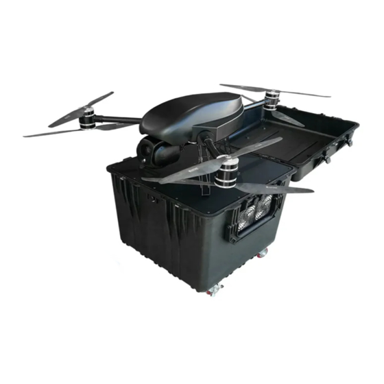
TS150 Warning: Any different reference you are looking for, please contact Embention 4.1.3 Power Station 4.1.3.1 Overview TS150 Power Station Overview 4.1. Part List... - Page 78 TS150 TS150 Power Station With Multicopter Chapter 4. Technical...
- Page 79 TS150 TS150 Power Station Ready to use 4.1. Part List...
-
Page 80: Exploded View
TS150 4.1.3.2 Exploded View TS150 Power Station 4.1.3.3 List Reference Description Quantity CEHW048 Emergency Stop Button EMMA008 Case EMMA009 4 Wheel Kit MTME269 Handle MTME270 M6 Knob Kit (4 units) MTME271 M5 Knob Kit (6 units) CECN362 230V AC input plug... - Page 81 TS150 TS150 Power Station Reference Description Quantity CEHW068 Dust filter Warning: Any different reference you are looking for, please contact Embention 4.1. Part List...
- Page 82 The NM& TS150 hexacopter is our multirotor tethered solution. The Tether Ground Station allows to power the UAV directly from an on-ground power source, providing unlimited flight time. Tether Station uses an innovative ultralight cable to connect the NM& TS150 drone to the ground station so the aircraft has a continuous power source during the operation.
- Page 83 TS150 NMAND TS150 Multirotor Tethered Station 4.1. Part List...
Need help?
Do you have a question about the TS150 and is the answer not in the manual?
Questions and answers